3
\$\begingroup\$

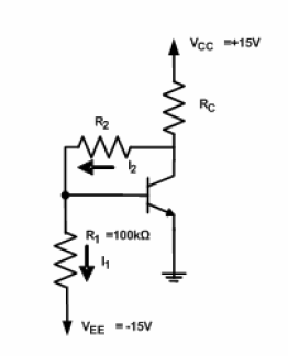
I have been given the followign circuit diagram:

enter link description here

and have been asked to compute \$R_2\$ and \$R_C\$ such that, at the Q-point, the circuit will behave as follows:

\$V_{CE}=5\:\mathrm{V}\$
\$V_{BE}=0.7\:\mathrm{V}\$
\$I_C=2\:\mathrm{mA}\$
\$\beta=100\$

(where \$\beta =i_c/i_b\$)

I'm really not familiar with this type of circuit display, can someone help explain how I can find the two needed resistances?

\$\endgroup\$
4
  • 3
    \$\begingroup\$ The answer is in many books. Learn!! And on the way there, come back here for answers to short and specific doubts. You shouldn't ask us to solve a whole problem for you. If your effort is zero, you will learn nothing. \$\endgroup\$
    – Telaclavo
    Commented May 16, 2012 at 21:02
  • 1
    \$\begingroup\$ A link to a source where such circuit displays are explained would be enough. The notes the professor provided for the class are inadequate. \$\endgroup\$
    – Neyo
    Commented May 16, 2012 at 21:07
  • 1
    \$\begingroup\$ You have to learn to learn. Think about what keywords would put you on the right track. There is a lot of material in internet. Think also about what books might help you. I'm sure you can borrow some, from your library. Or even buy some. Every good engineer has many books. \$\endgroup\$
    – Telaclavo
    Commented May 16, 2012 at 21:13
  • 1
    \$\begingroup\$ I'm not really an engineer, I'm studying computer science and have a side class on electronics. Anyway the main problem is I'm greek and i'm struggling to google the right terms in english; haven't found anything so far. \$\endgroup\$
    – Neyo
    Commented May 16, 2012 at 21:21

3 Answers 3

4
\$\begingroup\$

There are many places we can begin looking at this.

We know that the collector current is 2 mA, and that \$V_{CE}\$ is 5V. Since the emitter is at ground, the collector must be at 5V, and so the voltage across \$R_C\$ is therefore 10V: the difference between 5V and 15V. So \$R_C\$ must be \$10V/.002A = 5K\Omega\$.

Next, \$R_2\$ and \$R_1\$ which span a voltage from \$-15V\$ to \$+5V\$ must form a voltage divider such that the top of \$R_1\$ is at 0.7V (\$V_{BE}\$). Hint: the voltage divider spans a range of 20V, and the 0.7V transistor base voltage is 15.7V above the bottom of the voltage divider.

This approach assumes that we can ignore the base current because it is small. Often when analyzing transistor circuits we can do that, but not in this case because \$R_1\$ is such a high resistor. The voltage divider is not "stiff" at all with regard to the resistance in the base circuit of the transistor (which has no emitter resistor at all).

A more exact answer requires that we account for the base current. The transistor is carrying only 2mA of current, and so is nowhere near hard saturation, and so the base current is only 0.02 mA, or 20 micro-Amperes (2mA divided by \$\beta\$).

Determine how much current is flowing through \$R_1\$ from its resistance, and 15.7 voltage. The current flowing through \$R_2\$ is the sum of the transistor base current (.02 mA) and the current through \$R_1\$. Knowing the current through \$R_2\$ and the voltage across it, we can calculate its resistance.
\$\endgroup\$
11
  • \$\begingroup\$ Thanks, I think I'm begining to understand the circuit with what you said. I'm still puzzled though as to why there's Vee voltage in what I would guess should be a Vbb. \$\endgroup\$
    – Neyo
    Commented May 16, 2012 at 21:47
  • \$\begingroup\$ Don't worry about that. These Vbb, Vcc labels are largely just traditional nonsense. Why Vcc in the first place? Because Vc is the collector voltage, so Vcc is the voltage "beyond" Vc. See here: en.wikipedia.org/wiki/IC_power_supply_pin#History . What happens if you have a larger circuit in which some of the transistor emitters go to Vee, and some go to ground? I avoid these silly names when designing circuits and use descriptive network names or numeric ones like +V12 and -V12. \$\endgroup\$
    – Kaz
    Commented May 16, 2012 at 21:59
  • \$\begingroup\$ Fair enough. Concerning Ib, is it correct to say its direction is left to right? Meaning overall its I2=Ib+I1 (I know you already said "sum" but didn't know if you meant it like this or didn't take +/- into account) \$\endgroup\$
    – Neyo
    Commented May 16, 2012 at 22:48
  • \$\begingroup\$ Also, how do i find the voltage surrounding R2 again? \$\endgroup\$
    – Neyo
    Commented May 16, 2012 at 22:56
  • \$\begingroup\$ First, calculate the current going through R2. This current is the sum of two currents, because it forks into two destinations: the transistor base and R1. The base current is obtained from dividing the collector current by the transistor's beta. The R1 current is obtained from knowing the voltage across R1, and it resistance. Once we add these two currents, we know the current across R2, and since we know the voltage across R2, Ohm's Law gives us its resistance. \$\endgroup\$
    – Kaz
    Commented May 16, 2012 at 22:59
3
\$\begingroup\$

\$ I_1 = \dfrac{V_{BE} - V_{EE}}{R1} = \dfrac{0.7V - (-15V)}{100k\Omega} = 157\mu A \$

\$ I_2 = I_1 + I_B = I_1 + \dfrac{I_C}{\beta} = 157\mu A + \dfrac{2mA}{100} = 177\mu A \$

\$ R_2 = \dfrac{V_{CE} - V_{BE}}{I_2} = \dfrac{5V - 0.7V}{177\mu A} = 24294\Omega \$

\$ R_C = \dfrac{V_{CC} - V_{CE}}{I_2 + I_C} = \dfrac{15V - 5V}{177\mu A + 2mA} = 4593\Omega \$

Kaz assumed \$I_2\$ to be negligible and arrived at 5k\$\Omega\$ for \$R_C\$, that's an error of almost 9%. Don't assume too much. The 100k\$\Omega\$ may suggest a very small current, but the voltage is rather high, and it appears that that current is 8 times as high as the base current, or together almost 10% of the collector current!

\$\endgroup\$
3
  • \$\begingroup\$ True, the error of ~9% is high and we do need to know how to calculate exact values. But last time I was in the shop, they were out of 4593\${\Omega}\$ resistors. And a transistor with \${\beta} = 100\$ was also hard to find. With an estimated value of 5000\${\Omega}\$, I would have probably bought a 4700\${\Omega}\$ resistor. With the exactly calculated value of 4593\${\Omega}\$, ... I think the shop would have sold me the exact same resistor as being the closest match. So from that perspective, 10% is not too bad and that is what I mean when I say electronics is not an exact science ;o) \$\endgroup\$
    – jippie
    Commented May 17, 2012 at 7:29
  • \$\begingroup\$ @jippie - "they were out of 4593Ω resistors". Do you want one of mine? ;-) This is a theoretical exercise, and it's meant to learn how to do the calculation. In that case you want to do it right. \$\endgroup\$
    – stevenvh
    Commented May 17, 2012 at 7:45
  • \$\begingroup\$ I know, hence the bold print. But in my opinion what we all forget to learn/teach at electronics class is getting feeling for how circuits respond in practise. \$\endgroup\$
    – jippie
    Commented May 17, 2012 at 7:52
1
\$\begingroup\$

I'd start with estimating how large the resistors approximately are. That is the easy part as the voltages at every node are easily calculated from the given details. Then approximate the current through the resistors by neglecting base current and you can approximate the resistors. The base current can be neglected for estimations because it is much smaller than the collector current. This way you get a feeling of what the values you should come to. If your final values (without neglecting base current) is about +/- 10% then your calculations are probably right.

\$\endgroup\$
2
  • \$\begingroup\$ Doing the actual calculation with the correct values the first time takes only 4 equations. Why would you approximate first, and then still have to do the calculations to correct your errors? \$\endgroup\$
    – stevenvh
    Commented May 17, 2012 at 5:39
  • \$\begingroup\$ The first approximation I always do myself from the top of my mind and takes just a few seconds. I neglet a bit, round a little and as a result I can do a sanity check of the values I calculate. Then the second pass I take all required details in consideration (and I usually make some writing errors while scribling down the formulae and its values). I guess it is working around mild dyslectic eyes. \$\endgroup\$
    – jippie
    Commented May 17, 2012 at 7:21

Your Answer

By clicking “Post Your Answer”, you agree to our terms of service and acknowledge you have read our privacy policy.

Not the answer you're looking for? Browse other questions tagged or ask your own question.