1
\$\begingroup\$

I've got a question about electromagnetic induction. I've already done some research but I'm unable to find the easy solution.

I want to calculate somehow maximum voltage peak that will be induced in secondary coil in AC circuit. For sure I have all input data here.

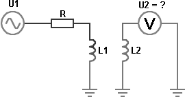
Circuit is obvious. There's primary air coil L1 connected trough a resistor R to sinewave AC voltage source U1 (oscillating with frequency f). Through the L1 coil flows AC current I.

I know every value here including L1 inductance, diameter, turns qty, winding wire radius and even non-ideal solenoid params like resistance and capacitance.

Next to the coil L1 there's secondary air coil L2, also with all known parameteres, and L2 is located next to L1 the distance l (in a straight line). L2 is contected to analog voltage meter to measure U2 voltage peaks.

Electric circuit:

enter image description here

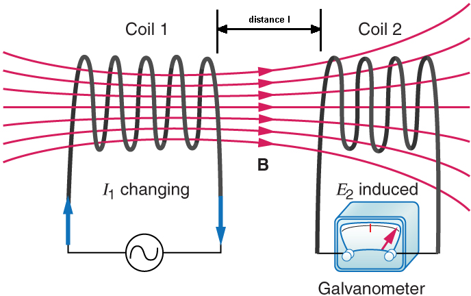
Coils phisical relation:

enter image description here

Question: How to calculate maximum voltage peak U2 that will be induced in the L2 coil? Does a simple, school formula U2max = ... even exists? Even poor approximation would be good enough.

\$\endgroup\$
2
  • \$\begingroup\$ For two coils L1, and L2 that are magnetically coupled, there exists a coefficient of mutual induction. For coil 1: U1 = L1di1/dt + M di2/dt. For coil L2: U2=L2 di2/dt + Mdi1/dt. Determining the magnitude of this M is another matter altogether. \$\endgroup\$
    – Bart
    Commented Aug 18, 2017 at 8:36
  • \$\begingroup\$ This link may help you to get a better understanding of coupled inductors: electronics-tutorials.ws/inductor/mutual-inductance.html \$\endgroup\$
    – Bart
    Commented Aug 18, 2017 at 8:41

3 Answers 3

1
\$\begingroup\$

There is no simple formula for Mutual Coupling.

But there are many books on the subject.

e.g. http://nvlpubs.nist.gov/nistpubs/bulletin/02/nbsbulletinv2n3p359_A2b.pdf

\$\endgroup\$
0
\$\begingroup\$

Short answer

If distance <= diameter_coils, then result is 'not too bad', and efficiency for power transfer can be salvaged by resonating the coils.

If distance > diameter_coils, then result is 'pretty bad', and you're really only going to be doing measurements, not power transfer.

Long answer

For each elemental loop in the transmit coil, there's a fairly simple equation for the field that the first produces through space, and for the emf that that generates in each elemental loop in the receive coil. Sum or integrate over all coils to give you the total.

Hint, the geometry stays simpler if the coils are co-axial, and simpler yet if identical.

Another hint, a few quick measurements of flat coils could replace the internet searches for the coupling equations. Consider each solenoid to consist of a small number of flat coils, and you'll have a huge improvement in accuracy compared to the amount of measurement work.

\$\endgroup\$
0
\$\begingroup\$

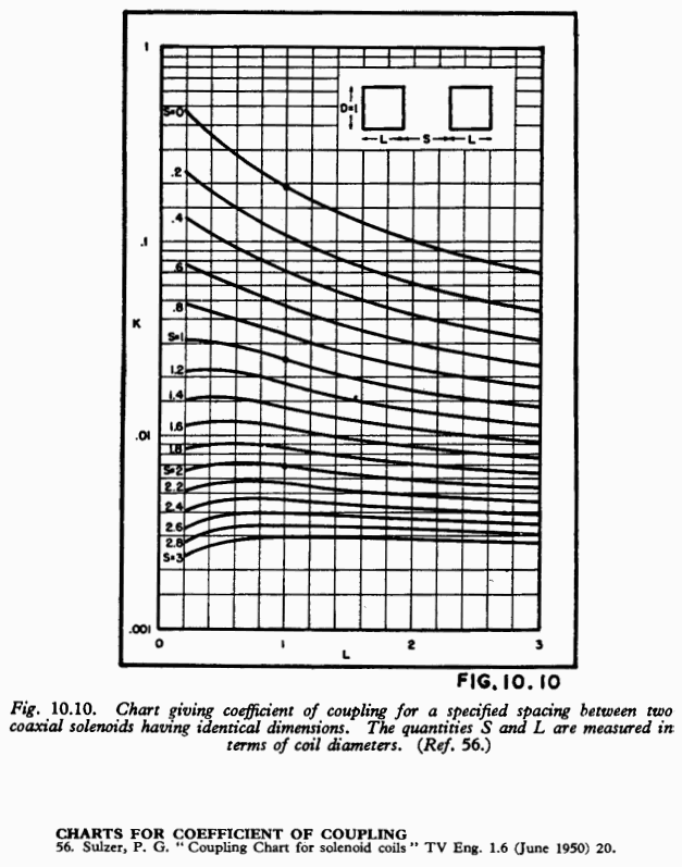
There are solutions to this in the back catalog. Consider the following plot:

enter image description here

Source: F. Langford-Smith, Radiotron Designer's Handbook, 4th ed. (1953), Wireless Press, p.447. Available in electronic form at: http://www.tubebooks.org/books/rdh4.pdf and other mirrors.

Coupling is less for axes misaligned, and zero for crossed axes (assuming the crossing point falls in one of the coils; oblique angles will still read something, due to one coil intercepting flux taking a return path around the other, and vice versa).

You don't give dimensions, orientation or geometry, so it's not clear if this is even applicable, but if the dimensions are not terribly far out, this should at least get in the right ballpark.

For another example, charging coils are an important topic these days, and relevant literature is abundant. See Degen, C. Inductive coupling for wireless power transfer and near-field communication. J Wireless Com Network 2021, 121 (2021) for example, particularly ref. 27 sounds useful.

Voltage can then be calculated from the mutual inductance, \$M = k \sqrt{L_P L_S}\$, \$V_P = L_P \frac{di_P}{dt} + M \frac{di_S}{dt}\$. Or for a less general case, the embedding networks/circuits can be modeled, and a simulation ran in any suitable simulator e.g. LTspice.

An excellent run-down for transformers, leakage, and relevant parameters, can be found here: Leakage inductance | Wikipedia

\$\endgroup\$

Your Answer

By clicking “Post Your Answer”, you agree to our terms of service and acknowledge you have read our privacy policy.

Not the answer you're looking for? Browse other questions tagged or ask your own question.