2
\$\begingroup\$

I have this frequency to analogue signal converter and I'm very confused about using it with NPN inputs.

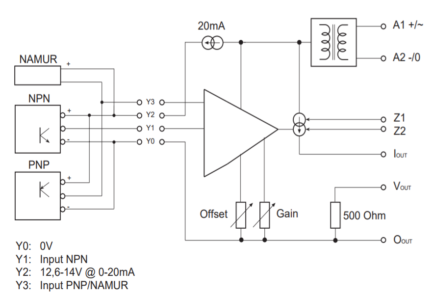
Here is the only block diagram they provide in their manual:

enter image description here

When I power this converter before wiring any input, I measure around 15V between Y1 and Y0 also 15V between Y2 and Y0.

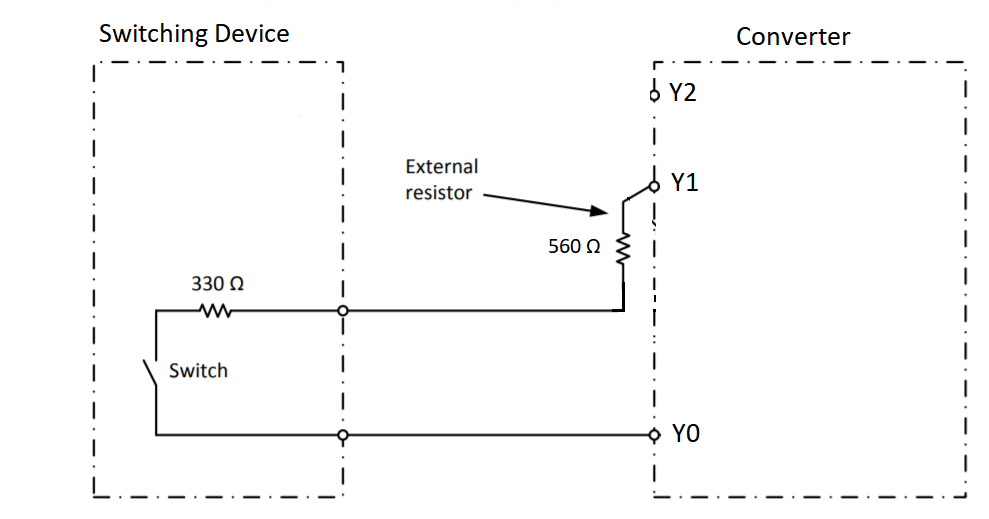
So here is how I wire a switching device to the converter:

enter image description here

When I wire like above and measure the voltage at Y1 by scope I see a pulse with low 5V and high 15V.

I didn't use Y2 at all. And some of the devices I need to hook up will output 0-5V pulse trains. I'm confused ad this point how to use NPN input here for a generic pulse input.

Is my wiring correct? How should it be used if the device already has pulse output? Should I use a transistor to use NPN input? A diagram would help a lot.

EDIT:

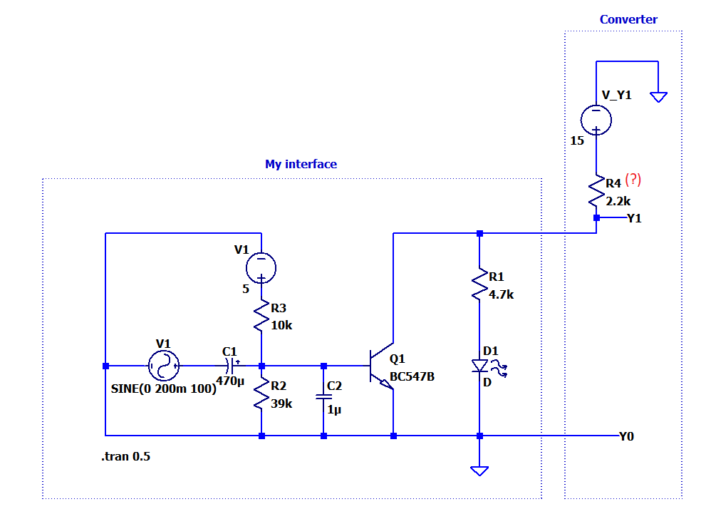
Here how I interface:

![enter image description here

The only thing I dont know when the transistor is ON, Y1 is directly grounded and how much current can flow. What I dont know is the output impedance the value of R4. I made a test and when I measure Y1 this way scope shows 0-10V pulses at the point Y1 so I adjusted R4 in simulation to have the same result. I didnt get any malfunction besides the ripple in analogue output of the converter. WHat do you think about my interface in my edit?

\$\endgroup\$

1 Answer 1

1
\$\begingroup\$

Your diagram is good for NPN input, except that your external resistance must be too high because the converter needs to see less than 5V when the switch is on (and >7.5V when it is off).

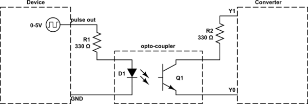
A device with 0-5V output will need an interface to convert the signal. For example if your device has sufficient output current to power an opto-coupler you could do this:-

schematic

simulate this circuit – Schematic created using CircuitLab

The reason for the opto-coupler is to isolate the device's ground from the converter. If the device is powered by the converter (via the Y2 and Y0 terminals) then you could just use an NPN transistor with Base resistor (valued to provide an appropriate bias current) or perhaps a logic-level MOSFET.

\$\endgroup\$
6
  • \$\begingroup\$ Thanks but couple of questions: 1) You wrote "except that your external resistance must be too high"; but in your example your external resistor is 330 Ohm less than mine. Do you mean to make the voltage at Y1 less than 5V the external resistor(R2 in your diagram) should be many kOhms? I dont get why.. 2) Do I also need an extra interface if I instead use PNP input for a device with 0-5V pulse output?(I would be so glad if you can add the PNP wiring to your answer) \$\endgroup\$
    – user1245
    Commented Aug 31, 2017 at 8:14
  • \$\begingroup\$ In your circuit the total resistance is 330+560 = 890 Ohms. If this drops 5V then the current is 5V/890 Ohms = 5.6mA. To get lower voltage you need less resistance. 330 Ohms would drop 330 Ohms * 5.6mA = 1.85V, which is safely below 5V. 330 Ohms matches the switch resistance in your diagram, but up to ~500 Ohms total resistance should be OK. \$\endgroup\$ Commented Aug 31, 2017 at 19:35
  • \$\begingroup\$ You still need an interface with PNP because the voltage levels (PNP/NAMUR: High > 5V Low < 2,5V) are not compatible. Also you still need an opto-coupler if the device does not have isolated output (if in doubt, include it!). The circuit for PNP is the same as NPN, except that you connect Q1 Collector to Y2 and Emitter to Y3. The only reason for having a PNP input is to support sensors which have PNP output, switching to + (Y2) rather than - (Y0). Since the optocoupler output is floating it doesn't matter which input you choose. \$\endgroup\$ Commented Aug 31, 2017 at 19:59
  • \$\begingroup\$ Thanks I tried NPN. Please see my edit at the end of my question I added the whole diagram with my interface, I made an interface and tested as shown. The only thing I dont know when the transistor is ON, Y1 is directly grounded and how much current can flow. What I dont know is the output impedance the value of R4. I made a test and when I measure Y1 this way scope shows 0-10V pulses at the point Y1 so I adjusted R4 in simulation to have the same result. I didnt get any malfunction besides the ripple in analogue output of the converter. WHat do you think about my interface in my edit? \$\endgroup\$
    – user1245
    Commented Aug 31, 2017 at 20:43
  • \$\begingroup\$ What is the advantage of isolating the device's ground from the converter's? Thanks \$\endgroup\$
    – user1245
    Commented Sep 3, 2017 at 15:22

Your Answer

By clicking “Post Your Answer”, you agree to our terms of service and acknowledge you have read our privacy policy.

Not the answer you're looking for? Browse other questions tagged or ask your own question.