1
\$\begingroup\$

I'm having trouble with a frequency converter. The data sheet is given here.

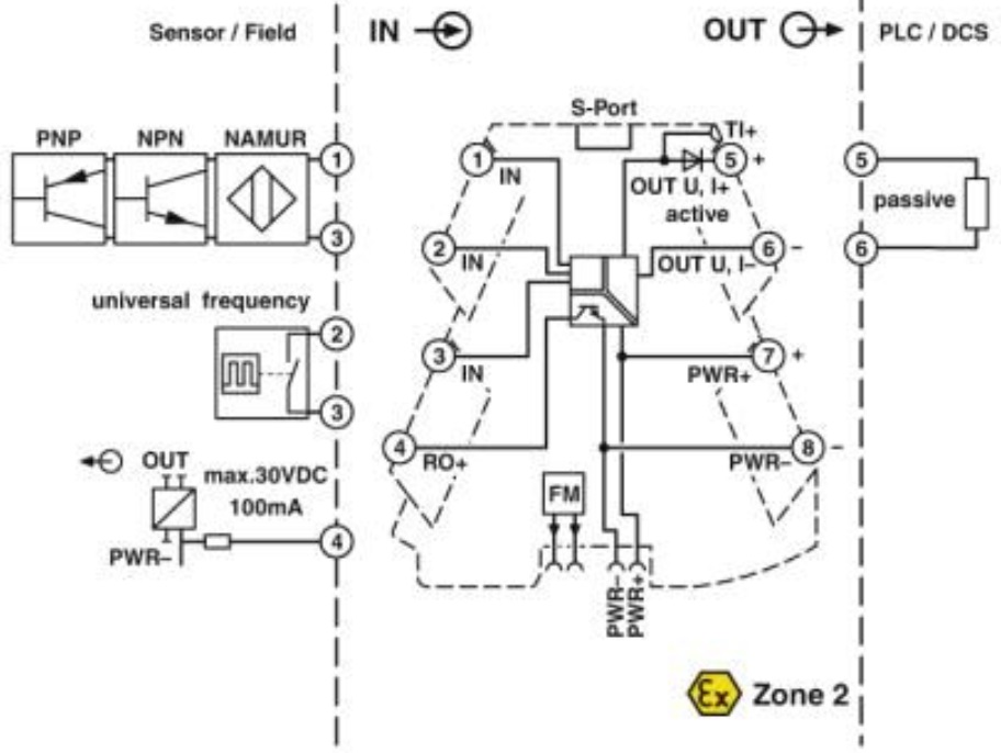
I set the converter for universal frequency input and voltage output. These can be configured by DIP switches. The diagram from the data sheet is given as below:

enter image description here

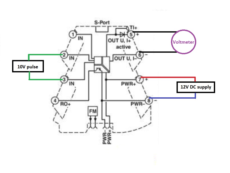
And here is how I do the wiring:

enter image description here

I use a 12V power supply, and as an input I couple 0/10V pulse train by using a function generator to the terminals 2 and 3 above. The pulse train is exactly 0..10V and I followed the advice on section 8.7 at page 20 to set the pulse properly.

I checked the DIP configuration too many times and I'm wondering whether my wiring is wrong. Just to make sure here is my DIP config:

For SW1: ON ON OFF OFF ON ON

For SW2: OFF ON OFF OFF OFF ON OFF ON OFF OFF

According to the data-sheet if I configure the DIP switches as above I should get 0 to 5V voltage output mapped from 1Hz to 300Hz frequency input range from a pulse train input.

But I get a constant 17.6V output by the voltmeter whatever the input frequency is, it is constant even though I don't hook up any input. The RED indicator flashes with 2.8Hz which data sheet says(at page 21) it happens when the "Sensor fault or invalid DIP switch configuration".

I spent several hours but no luck. Is the connection from the function generator to the terminals 2 and 3 correct?

\$\endgroup\$
2
  • \$\begingroup\$ 2-3 looks like a switch closure, not a voltage. \$\endgroup\$
    – rdtsc
    Commented Sep 4, 2018 at 18:16
  • \$\begingroup\$ 2-3 terminals are named as universal freq with pulse train sign. I thought that's the input for a pulse train. How could I make use of this if I want to convert an incoming pulse train by using this converter? \$\endgroup\$
    – cm64
    Commented Sep 4, 2018 at 18:20

2 Answers 2

1
\$\begingroup\$

For SW1: ON ON OFF OFF ON ON

You have configured "Universal Input Frequency to 0-5V". That's a relay input.
I'd would have used PNP input, but the manual is definitely not clear on this.
(as expected from Phoenix Contact)

For SW2: OFF ON OFF OFF OFF ON OFF ON OFF OFF

1 to 300 hz, software configuration active.

You've set all the DIP switches, but you've forgot to enable dip 10, enabling the dip switches as active configuration.


New info from comment. With this sensor (Adolf Thies 4.3351.00.000) the output is push-pull. Similar to the function generator. However, you need to change the range significantly for 1082 Hz at 50 m/s (22 Hz per m/s)
Try DIP2: [ON ON] [OFF ON ON ON ON OFF] [OFF ON]
10 Hz to 1200 Hz DIP configured, 10 Hz is 1 BFT, 1200 Hz is beyond 12 BFT

\$\endgroup\$
2
  • \$\begingroup\$ Oh thanks I see you are right. I had to enable by pin 10. Thanks. And if I have a pulse train as input what would be a better option. I will actually use this sensor as input biral.com/wp-content/uploads/2015/01/firstclassWSanalog.pdf It says it has push pull output and open drain. \$\endgroup\$
    – cm64
    Commented Sep 4, 2018 at 18:50
  • \$\begingroup\$ Yes 0 to 300Hz was for example. Thanks. But Im still confused whether terminal 2 3 for pulse input or relay input because it mentions on section 8.7 at page 20 to set the threshold. \$\endgroup\$
    – cm64
    Commented Sep 4, 2018 at 19:17
1
\$\begingroup\$

If Joroen's answer doesn't solve the problem I note that there is a app to configure certain options.

Page 1, Description states:

You can optionally configure the device using DIP switches, or with enhanced functionality via the S-PORT using the standard Analog-Conf software via FDT/DTM, or without further accessories using the Mini Analog Pro Smartphone app.

Page 20 states:

8.7 Frequency input threshold

For universal frequency input a measuring threshold must be employed.

The measuring threshold should be in the center of the frequency signal's amplitude.

When measuring, ensure that all negative components of the signal are cut. You must therefore place the measuring threshold exactly in the center of the positive part of the amplitude.

It seems to me that you may have to set your threshold to 5 V to detect your 0 to 10 V signal correctly. (But I don't know!)

\$\endgroup\$

Your Answer

By clicking “Post Your Answer”, you agree to our terms of service and acknowledge you have read our privacy policy.

Not the answer you're looking for? Browse other questions tagged or ask your own question.