I have this frequency to analogue signal converter and I'm very confused about using it with NPN inputs.
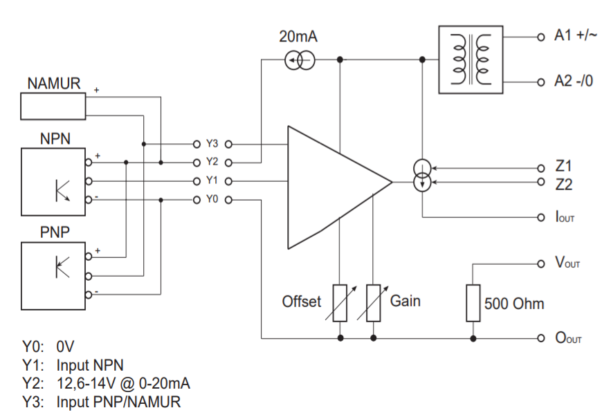
Here is the only block diagram they provide in their manual:
When I power this converter before wiring any input, I measure around 15V between Y1 and Y0 also 15V between Y2 and Y0.
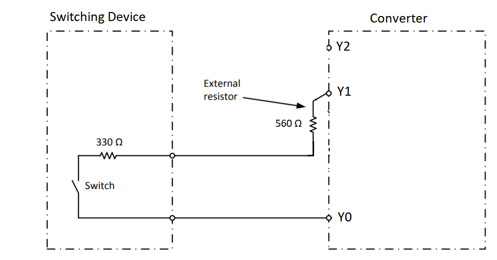
So here is how I wire a switching device to the converter:
When I wire like above and measure the voltage at Y1 by scope I see a pulse with low 5V and high 15V.
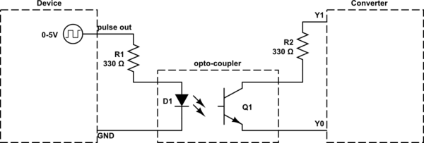
I didn't use Y2 at all. And some of the devices I need to hook up will output 0-5V pulse trains. I'm confused ad this point how to use NPN input here for a generic pulse input.
Is my wiring correct? How should it be used if the device already has pulse output? Should I use a transistor to use NPN input? A diagram would help a lot.
EDIT:
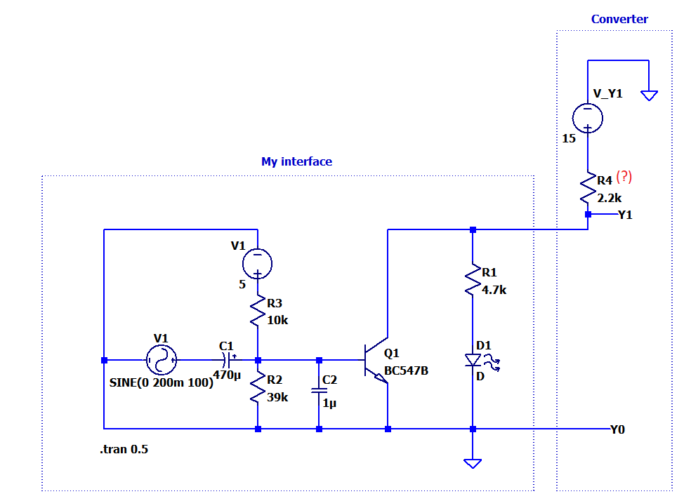
Here how I interface:
The only thing I dont know when the transistor is ON, Y1 is directly grounded and how much current can flow. What I dont know is the output impedance the value of R4. I made a test and when I measure Y1 this way scope shows 0-10V pulses at the point Y1 so I adjusted R4 in simulation to have the same result. I didnt get any malfunction besides the ripple in analogue output of the converter. WHat do you think about my interface in my edit?


