1
\$\begingroup\$

I'm trying to replace the old NiMH Roomba battery with a bunch of 18650s recycled from old laptops. Lucky enough Roomba uses 12s NiMH battery, that operates in a voltage range of 12-18 V, and has quite similar characteristics to a 4s Li-ion battery: 12-16.8 V.

After adding a simple 4s protection board, it seems to work fine and generally does the job. There's one small caveat I'm trying to tackle - Roomba's charging circuit complains about the battery when the protection board cuts the current to prevent a cell from overcharging and the robot reports a "Charging Error 5".

I'm guessing that it's just because the battery is unable to reach a voltage higher than 16.8 V. I also know that people solve this issue somehow without modifying the Roomba itself - there are third-party Li-ion batteries available on the market. Is there any simple solution that'd allow preventing the error message?

I thought about connecting a capacitor to the output to allow charging to a higher voltage when the battery gets cut, but it doesn't work - it'd need to have a very high capacity to work properly, I think.

\$\endgroup\$
4
  • 1
    \$\begingroup\$ Two diodes in series before the protection board will drop ~1.2V. \$\endgroup\$
    – Dampmaskin
    Commented Sep 4, 2017 at 10:31
  • \$\begingroup\$ …and prevent it from either: charging or discharging (depending on polarization). Am I correct? \$\endgroup\$
    – kuba
    Commented Sep 4, 2017 at 10:51
  • 1
    \$\begingroup\$ If it discharges through the same wire, yes. Then you need a Schottky diode in antiparallel. \$\endgroup\$
    – Dampmaskin
    Commented Sep 4, 2017 at 10:56
  • \$\begingroup\$ There's a good Roomba charge limiter project here: github.com/nickshl/RoombaChargeLimiter \$\endgroup\$
    – vzaremba
    Commented Feb 3 at 16:43

2 Answers 2

1
\$\begingroup\$

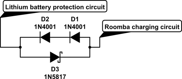
Two silicon diodes in series should be able to drop the required 1.2V (or a little bit more) from 18V to ~16.8V when charging.

When discharging, a Schottky diode in antiparallel will let the current flow back out of the Lithium battery circuit with only a small voltage drop.

Something like this:
schematic

simulate this circuit – Schematic created using CircuitLab

This assumes that the same wire is used for charging and discharging, and that the circuits behave as you have described.

In the real world you may or may not need to tweak some additional things to make it work, but in principle this should do it.

Take care to use diodes that can take the necessary current and dissipate the power.

The Schottky diode should have as low a voltage drop as possible. The reverse breakdown voltage of the Schottky doesn't need to be very high though, since the regular diodes are limiting that voltage.


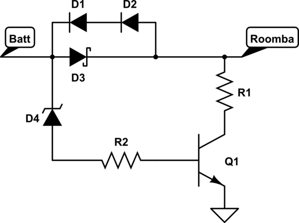
If the Roomba charger is looking for a dip in voltage that indicates that the battery is full, the circuit will have to be more complex. Perhaps a shunt resistor and a transistor triggered by one or more zener diodes would work, something like this:
schematic

simulate this circuit

You would have to choose the right Zener voltage(s) to trigger the transistor right before the Lithium battery protection circuit reaches its cutoff voltage. R2 should limit the base current of the transistor, while R1 pulls the voltage at the Roomba charger output down. R1 needs to be able to:

  • Pull down the voltage at the Roomba charger output by ~5 mV per cell in the NiMH pack, to simulate a full NiMH battery.
  • Handle the full 18V for however long it takes for the charger to realize that the battery is full and stop charging.

And the transistor needs to be able to withstand the same current.

A circuit like this should be tested thoroughly before put into use, though. If the charger doesn't trigger and shut off correctly every time, you might risk R1 getting hot enough to set something on fire, that's of course depending on how much power it will have to dissipate. You can run the numbers and even simulate some circuits, but also don't forget to run enough real-life tests.

BTW, if the Lithium-ion protection board has a LED (or some output pin) that turns on (high) when it reaches max voltage and cuts off, you might be able to use that output to trigger the transistor instead of using a zener diode.

\$\endgroup\$
4
  • \$\begingroup\$ I added 2 diodes in series at the beginning, but it didn't solve the problem. I ended up with 4 diodes plus a Schottky, but the charging error still occurs. The charging circuit seems to be more sophisticated than expected. Thank you for your help, please let me know if you have a different solution. \$\endgroup\$
    – kuba
    Commented Sep 5, 2017 at 14:31
  • \$\begingroup\$ I have updated my answer with some additional thougths. \$\endgroup\$
    – Dampmaskin
    Commented Sep 5, 2017 at 15:09
  • \$\begingroup\$ Thank you for your help - I'll try to test the suggested approach soon. The Li-Ion protection board uses 8254AA chip, according to its specification the COP pin behaves pretty much like you described. It outputs high state when one cell reaches the maximum voltage to drive the N-channel MOSFET and interrupt the current flow. I think it might be useful for simulating the voltage drop too. \$\endgroup\$
    – kuba
    Commented Sep 6, 2017 at 11:33
  • \$\begingroup\$ Sounds good. A power NMOS can be a good candidate for Q1 if you use the protection board to drive it. If you go for the Zener approach, a Darlington pair might be necessary to get enough gain. \$\endgroup\$
    – Dampmaskin
    Commented Sep 6, 2017 at 13:50
-1
\$\begingroup\$

One simple way to achieve the end of charge would be to use a zener to activate a resistor that heats up the protection thermistor. The Roomba will think the ni-mh is getting overcharged and will stop the charging process...

\$\endgroup\$

Your Answer

By clicking “Post Your Answer”, you agree to our terms of service and acknowledge you have read our privacy policy.

Not the answer you're looking for? Browse other questions tagged or ask your own question.