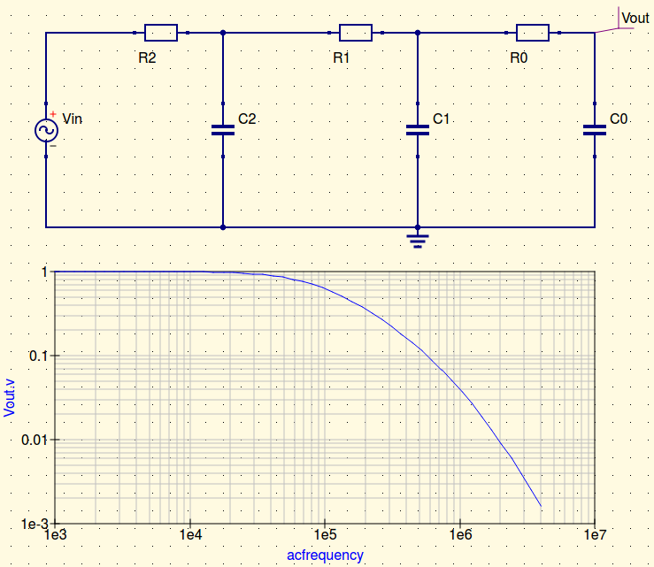
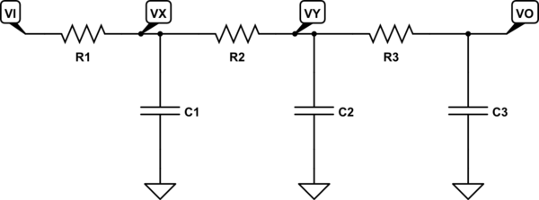
You can determine this transfer function without writing a single line of algebra by using the fast analytical circuits techniques or FACTs. What you need to do is determine the natural time constants of this circuit when the excitation (\$V_{in}\$) is reduced to 0 V or replaced by a short circuit in the schematic. Then, you "look" at the resistance offered by each of the energy-storing elements (the capacitors in this example) in dc or in high-frequency. Look at the below sketch:
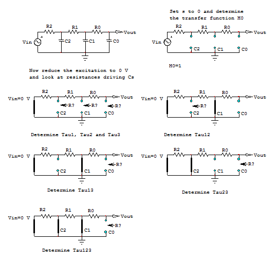
First, you look at the transfer function \$H_0\$ for \$s=0\$: open all the caps and find that \$H_0=1\$. Then, determine by inspection - meaning, just observe the schematic - the resistance offered by each capacitor's connecting terminals when the other caps are set to their dc state (infinite impedance or removed from the circuit). In this mode, the excitation source is reduced to 0 V and replaced by a wire in the schematic. For \$C_1\$, the resistance you "see" is the series connection of \$R_1\$ and \$R_2\$ so the first time constant is \$\tau_1=C_1(R_1+R_2)\$. For \$\tau_2\$, the resistance is \$R_2\$ then \$\tau_2=C_2R_2\$. And for \$\tau_3\$, the resistance is \$R_1+R_2+R_0\$ then \$\tau_3=C_0(R_1+R_2+R_0)\$. Adding these time constants forms the first denominator coefficient \$b_1=\tau_1+\tau_2+\tau_3\$. 1 mn to obtain this result without a calculation, just inspection.
For the second term, \$b_2\$, we will look at \$\tau_{12}\$, \$\tau_{13}\$ and \$\tau_{23}\$. This notation simply means that for \$\tau_{12}\$, you "look" at the resistance driving \$C_2\$ while \$C_1\$ is set in its high-frequency state (a short circuit). For instance, looking at the above sketch, you see that \$\tau_{12}=C_2(R_1||R_2)\$. Continue and form \$b_2=\tau_1\tau_{12}+\tau_1\tau_{13}+\tau_2\tau_{23}\$.
For the final term, \$b_3\$, determine \$\tau_{123}\$: look at the resistance from \$C_0\$ terminals while \$C_1\$ and \$C_2\$ are set in their high-frequency state (a short circuit). Then, assemble \$b_3=\tau_1\tau_{12}\tau_{123}\$. This is it, you have your denominator \$D(s)=1+sb_1+s^2b_2+s^3b_3\$ and the transfer function is immediate and equal to
\$H(s)=H_0\frac{1}{1+sb_1+s^2b_2+s^3b_3}\$.
with:
\$b_1=R_1C_1+R_2(C_1+C_2)+C_0(R_1+R_2+R_0)\$
\$b_2=C_1(R_1+R_2)(C_2(R_1||R_2)+R_0C_0)+R_2C_2C_0(R_1+R_0)\$
\$b_3=C_1C_2C_0R_1R_2R_0\$
Now, this 3rd-order polynomial form can be rearranged under different expressions, depending on how the poles are organized. If they are well spread, you can factor \$D(s)\$ as \$D(s)\approx (1+b_1s)(1+\frac{b_2}{b_1}s)(1+\frac{b_3}{b_2}s)\$. If two poles are close to each other, then one pole dominates while a second-order polynomial form appears for the two coincident poles. I have captured all these expressions as well as the raw reference expression obtained using Thévenin (to compare the derived results to) and they all match perfectly. See the below Mathcad shots:
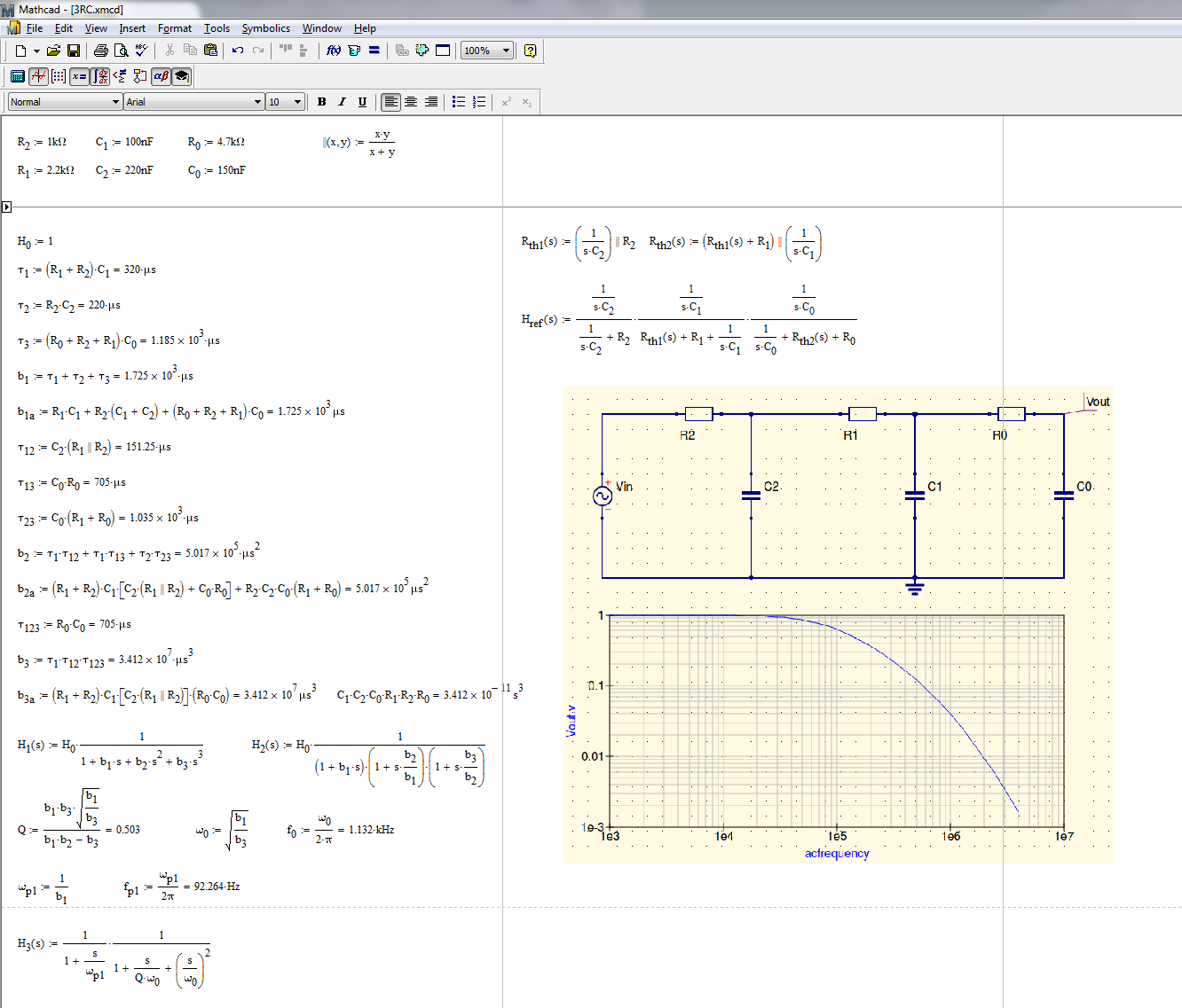
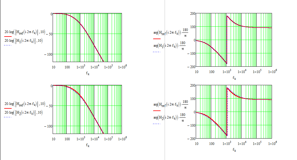
As you can see with the FACTs, I did not write a single line of algebra and chopped the original schematic in a series of small sketches individually observed. That means that if I spot an error between the raw expression and my canonical form, I can go back to the small sketch and correct the guilty one immediately. Should you use KVL/KCL and find a mistake, good luck to correct it without restarting from scratch. FACTs are truly the way to go and I encourage students to acquire this skill.
