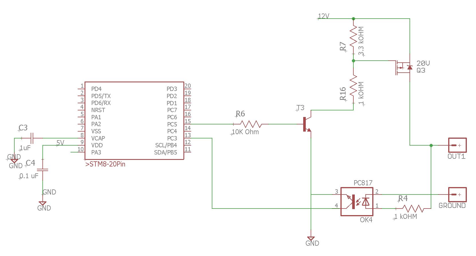
The Below mentioned circuit switches 12V when the OPTO sense high voltage
The Strings of LEDs is connected to OUT1 and also an SPST switch is also connected externally (not shown in image). The Switch is connected to 12V on side and another side to OUT1.
When Switch(SPST) is ON, i.e 12V is short with OUT1 for short time, the OPTO senses High-level voltage and MCU turns on the MOSFET producing flashing effect at OUT1. The moment MOSFET is turned ON, there will be high voltage at the OPTO as well as at the OUT1. This won't have any effect until the OPTO continuously senses High Voltage for 5 secs and MCU will turn off the MOSFET, which will happen only when the switch (SPST) is short for 5 secs, the output from MOSFET will in switching state (1sec on/off), so it can't be continuous of 5 secs.
The 5 secs delay in sensing is used to differentiate between the Actual high voltage from the switch(SPST) and the output from MOSFET.
Now the issue is with 5 sec delay which is undesirable, 1sec can work but with the kind of switching pattern, it will overlap and the everytime pattern starts the MCU will shut it off.
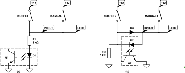
How can the circuit be modified with very fewer components so that, the voltage from the MOSFET side does not go to OPTO and only goes to the OUT1 ? And Whenever Voltage comes from the OUT1 Connector, the Opto should sense that.


