1
\$\begingroup\$

Based on the well-known Inventable.eu article, I combined their CMOS timer PWM with adjustable duty cycle with logic that switches the supply to the timer circuit. Only when the gate conditions (AND; both signals are true) are satisfied is 12V supplied to the rest of the circuit.

The following image represents the circuit I have built:

Circuit comprising a 5V voltage regulator, comparator with photo resistor, an AND gate combining the output of the comparator and the output of an external logic signal to produce a signal to switch a pFET that turns on a 555 CMOS timer configured to dim 12V LED strips using PWM.

My problem is achieving a ramp down effect when the 12V supply to the timer sub-circuit is shut off. My first attempt was an RC network at the base of Q4, but this only delayed the switch off and did not produce the desired fade out effect. For my second test, I added a 1000uF capacitor in parallel with the 560uF listed in the schematic. The resulting delay was too short.

My question: how to introduce a delay without compromising the pulse switching Q5. One possible solution is outlined here, but I am unsure how this could be adapted, and want some other options before salvaging the necessary opto isolator device.

Can you please explain in your answer how your solution interacts with the timer's PWM and the rest of the circuit, particularly the high side switching at Q2. Thank you.

Update: based on Mr. Tony Stewart's comments, it appears my design may simply be incompatible with any sort of off-ramp. While there are perhaps options involving the 555's reset in place of the high side switch, I prefer keeping it as-is, if only for the lower current consumption.

\$\endgroup\$
8
  • \$\begingroup\$ Ramp down requires significant Cap storage energy for low ESR LED's and low tolerance to voltage decay. What are your specs for decay time, LED power. Vmax-Vmin and thus C required to meet T is strongly dependent on LED ESR * C and decay voltage tolerance. e.g. ESR * C=8T implies a huge cap for 10% voltage decay. What load, ramp time and ΔV? \$\endgroup\$
    – D.A.S.
    Commented Apr 5, 2017 at 2:56
  • \$\begingroup\$ where is 1MF ? 1000 uF? I see C5 470uF. If load is 1A LEDs that is 3S x 3V or 3 * 3W , this has ESR of 1Ω , thus 1000 uF decays LED current ramps down << 1 millisecond. capiche? So if my assumptions of your application are close, not possible. If wrong and 12V stays on but you just want a slow disable off, answer above queries and clarify response. \$\endgroup\$
    – D.A.S.
    Commented Apr 5, 2017 at 3:12
  • \$\begingroup\$ I'm aghast that anyone would try to do this with a 555 timer and analog logic like this. This is a job for $1.50 MCU. \$\endgroup\$ Commented Apr 5, 2017 at 3:45
  • \$\begingroup\$ @TonyStewart.EEsince'75 For testing, I am using 1m of 12V led strip, which draws 150mA. Final application will use 2.8m of LED strip, roughly 420mA. LEDs light at >6V (3 in parallel with 150Ω). 4 second drain from 12V to 6V is thus the objective. This gives the occupant of the room time to trip the motion sensor before it goes completely dark. \$\endgroup\$ Commented Apr 5, 2017 at 20:52
  • \$\begingroup\$ @TonyStewart.EEsince'75 I added the 1000uF on my breadboard in parallel with the 470uF, as well as at the supply for the LED (CONN_01x02, net labels did not print -- pin 2 of Q5 drains to the connector). With 1m of LED, the fade was a fraction of a second. \$\endgroup\$ Commented Apr 5, 2017 at 20:55

2 Answers 2

1
\$\begingroup\$

If you dont want to use an MCU. I think you should give a shot at Farad super capacitors.

For your application it is hard to find a super capactior that can operate on 12 V so you have to make different combinations of capacitors (series/parallel).

If you use 5V LED strips it would be way better since there are already 1F 5V super capacitors available. Then you should make your calculations to find out how many capacitors you should use.

Have a look here and here to find the super capacitor that meets your needs.

\$\endgroup\$
0
\$\begingroup\$

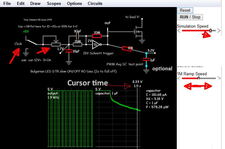
Since someone in Bulgaria wanted the same thing for his LED Day Time Running Lights with variable ramp On / Off time , I decided to do a quick design , which is my own invention here for you guys.

It works quite simply by the Relaxation Oscillation like a 555 ( which I have chosen never to use for obscure professional reasons.)

CMOS Schmitt triggers come in various packages with 6 per SOIC14 and have a typical threshold that is used in this design from 1/3 to 2/3 of Vcc. HC14 for 5V logic and others up to 20V logic and Schmitt NAND gates , and works on all the same ( more or less)

I use a 1.5:1 resistor ratio use match this hysteresis range in the DC slew control to frequency delay feedback R of this Relaxation oscillator. This results in disabling the clock then ramping thru 0% to 100% duty cycle and then off again.

If you have any good questions go ahead. Here's my quick and dirty "two-bits" PWM ramp dimmer for any MOSFET driver. It uses the 74HC14 for 5V or the HCF4093 20V CMOS NAND Schmitt trigger if you want to disable with another input.

A PD photo sensor and RC filter with another gate could be used as night sensor with correct bias for light current and cap to avoid transients using a NAND Gate or Inverters.

It was design to turn on the lights after Power On then return to the input logic control state with a ramp time from 0 to 20 seconds using a 1M pot and 10uF Cap.

The delay after switch is a fraction of the total RC time constant which is about half of the 0 to 100% ramp time.

This is not a completed design, just a quick and dirty solution.

The PWM clock actually speeds up in the 1~2 Khz range as it goes thru the 50% PWM zone then slows down at each limit but does not affect the PWM duty cycle.

FALSTAD SIMULATION with manual toggle switch

Enjoy.

enter image description here

Press Reset top right to start from Time T=0 and adjust slo-mo simulation speed to desired speed and below that adjust pot slide off to ramp speed.

Click switch (left ) to toggle input ( Use another inverting gate ,as this is negative logic)

Also if you want a slight mod makes a manual dinner. For U to figure out . If someone makes a good little PCB, I'll buy it.

\$\endgroup\$

Your Answer

By clicking “Post Your Answer”, you agree to our terms of service and acknowledge you have read our privacy policy.

Not the answer you're looking for? Browse other questions tagged or ask your own question.