0
\$\begingroup\$

I would like to power a small internet access point about 250m (800ft) away from my home (rural).

The wifi unit and modem draws about 16W max @ 12v. I had originally planned to power this via solar, but after some calculations of cost of the panel and batteries, and the physical size of the mounting required for the panels (very windy here) I started looking at other options.

Direct bury cable garden is really expensive here (New Zealand) but a box of cat5e - even the direct bury stuff isn't too bad.

I was wondering if I could run Cat5 the 250m, use all 4 pairs for power. I understand there will be a voltage drop along the run, and some wire resistance to consider - but could i use a higher input voltage and the regulate back to 12v at the remote end?

The box of Cat5 says each conductor is 24 AWG - about 0.5mm

I was hoping someone here could help be with the maths on voltage drop, current capacity etc

Is it workable or am I back to a solar option?

thanks dave

\$\endgroup\$
3
  • 3
    \$\begingroup\$ Possible duplicate of Why is there a voltage drop in a twisted pair wires of an UTP cat.5 cable? \$\endgroup\$
    – Passerby
    Commented Nov 2, 2017 at 23:10
  • \$\begingroup\$ That question answers everything you need to know about this. Simple answer depending on the resistance, you will need to up the voltage significantly then regulate it down at the end. \$\endgroup\$
    – Passerby
    Commented Nov 2, 2017 at 23:11
  • 1
    \$\begingroup\$ There is a type of AC mains wire called UF (underground feed) wire in the USA. Maybe you have something similar. This is a direct burial wire. Just run AC mains to the wifi unit. Should not be any more expensive than direct burial cat5. Use the smallest diameter available. Or you could run 48 VDC through the UF cable, and put a buck converter at the far end to regulate down to 12V. Basically, for such a long run, it is worth it to go to a higher voltage across the wire. Use a fuse somewhere to make sure the wire ampacity is not exceeded due to fault conditions. \$\endgroup\$
    – user57037
    Commented Nov 3, 2017 at 3:10

3 Answers 3

1
\$\begingroup\$

Power over Ethernet is the generic term for what you are describing. There is a widely adopted IEEE standard for the technology (IEEE802.3) and a thriving market for compatible equipment, although custom implementations are also used in some cases. The standard might allow you to do exactly what you want. Assuming you already need to run twisted pairs for data, you can also use the same cable for power. Type 2 (PoE+ or 802.3at) systems are designed for power levels up to 25W (the system voltage is about 50V).

You may not need some of the safety/handshaking/robustness features that an IEEE compliant solution provides, but you could take advantage of off-the-shelf equipment to get up and running quickly. You would want something marketed as a "PoE injector" where your mains are located and something sometimes called a "PoE splitter" on your load side. You can find these with a DC-DC converter built in that will provide 12V at your remote location. In the U.S., each of these can be found for less than $20. Make sure that the power level matches your needs (the 802.3af or "Type 1" only guarantees 12W at the load) and that it is compliant with your data standard (if you are diplexing the cable).

That being said, you can certainly spin your own solution. The standard (and its market) have dealt with substantial challenges like supply inrush, cable surge, etc. that might cause you headaches along the way. Good luck either way!

\$\endgroup\$
1
  • \$\begingroup\$ I looked at PoE, but because of the distance it would need PoE repeaters along the cable. I've not seen these used before. \$\endgroup\$
    – dave
    Commented Nov 3, 2017 at 2:20
0
\$\begingroup\$

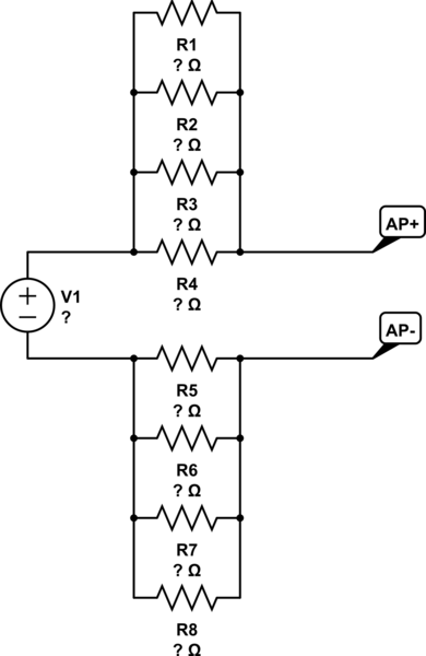
In such a scenario, you would treat each conductor in the cable as a resistor. Since CAT5 cable has 4 twisted pairs, you could dedicate 4 conductors each to power and ground. This is analogous to putting 4 resistors in parallel, so your circuit basically becomes this:

schematic

simulate this circuit – Schematic created using CircuitLab

Calculated using the parameters found at this link, the resistance of 250m of 24AWG single-core wire is (88ohms/km)(0.25km) = 22ohms. Using the formulas for equivalent resistance, you can find that four 22-ohm resistors in parallel has an equivalent resistance of 5.5ohms.

Using Ohm's Law, you can figure out the voltage drop across each conductor. You said your AP draws 16W @12V, so it draws 16W/12V = 1.33A (let's be conservative and call it 1.5A). The voltage drop from 1.5A running through a 5.5ohm resistor is (1.5A)(5.5ohms) = 8.25V. Since current flow through all components in a series circuit is equal, each set of four conductors will drop 8.25V, so you would need a power supply of at least 2 * 8.25V + 12V = 28.5V, plus whatever the dropout voltage is of the regulator you choose to install at the end.

However, one thing you need to consider is that all the power dissipated by the wire turns into heat. When a current enters a junction of four equal resistors, the current is divided equally among them, so (1.5A/4) = 0.375A of current flows through each conductor. The power dissipated by each conductor can then be found using P = I^2R = (0.375)^2(22) = 3.09W. This is quite a bit of power to dissipate in a wire and could heat it up considerably.

\$\endgroup\$
6
  • 1
    \$\begingroup\$ 3W won't heat up 250m of cable to a noticeable extent - that's a lot of copper. \$\endgroup\$
    – user16324
    Commented Nov 3, 2017 at 0:14
  • \$\begingroup\$ I figured as such - I just don't know enough about the thermal capabilities of wire to make a definitive statement about it :p \$\endgroup\$ Commented Nov 3, 2017 at 0:28
  • \$\begingroup\$ So that looks like its workable then, but with some loss in the cable. Would I be correct in saying the if I'm pulling in 30V @ 1.5A that's 45W of power in to get 18W at the far end. I pay about 20 cents for unit of power, so to run this @ 45W it will cost me about $8 per year. If my maths is right there is no way a solar solution would ever pay for itself. \$\endgroup\$
    – dave
    Commented Nov 3, 2017 at 2:13
  • \$\begingroup\$ Yep! There's quite a bit of loss in the cable; it may not be an efficient solution but it will work if it's what you have on hand \$\endgroup\$ Commented Nov 3, 2017 at 2:15
  • 1
    \$\begingroup\$ Or put 30V at .7 amps and regulate it down. Less power loss and voltage drop. \$\endgroup\$
    – Passerby
    Commented Nov 3, 2017 at 2:43
0
\$\begingroup\$

24 AWG for 250 meters works out to about 20 Ohms. Using all four pairs should reduce that to approximately 5 Ohms.

16 watts at 12 volts means 16/12= 1.34 amps.

1.34 Amps through 5 Ohms means a 6.7 volt drop in the wire, and about 9 watts lost in the wire.

So, if you wanted to do this directly, you'd need to start with at least 18.7 volts and 25 watts at the source to meet your requirements at the target.

The losses in the wire depend on the current, not the voltage though. If at all possible, you'd be much better off transmitting higher voltage at lower current. For the obvious example, if you used power from the wall (240 volts) you could use a normal 12 V power supply at the far end.

Let's assume your power conversion at the far end is 80% efficient, so to get 16 watts out, you need 16/0.8 = 20 watts in. At 240 volts, 20 watts means about 84 mA. That gives a loss in the wire of roughly 0.4 volts, and 35 mW.

In short, in this case you don't really need to do much of anything to compensate the wire. Simply for safety, you might want to use an isolation transformer, and probably a fuse/circuit breaker specifically for this circuit. Given the requirements, something like 1/10th or 1/8th amp would be adequate.

Most Cat 5e cable I've seen is rated for around 300 or 350 volts1, so running 240 volts through it shouldn't be a real problem. Most is rated only for indoor use though, so using it outdoors might not work out so well (e.g., insulation might not withstand the UV in sunlight well, and might deteriorate fairly quickly). Ideally, you'd like it to be outdoor rated, but that may not be as inexpensive as what you're currently considering.

On the other hand, as @mkeith pointed out in a comment, carrying a high voltage on a cat 5 cable is sufficiently unexpected that it carries a degree of danger, even when/if the cable itself is rated for that voltage. It's probably safer to reduce the voltage somewhat, and put up with greater loss in the cable (though you might consider some middle ground, where you use a voltage somewhat higher than the 12 volts required by the router, but still lower than the 240 supplied from the socket--perhaps 48 volts, for example).


  1. For one example: UL Voltage Rating: 300 V RMS.
\$\endgroup\$
4
  • \$\begingroup\$ If using 240 volts, the OP will require cable rated for 240 volts, and rated for direct burial (or suitable conduit). You shouldn't use cat5 cable for 240 volts. \$\endgroup\$ Commented Nov 2, 2017 at 23:30
  • \$\begingroup\$ @PeterBennett: Most Cat 5e (at least that I've seen) is rated for more than 240 Volts. \$\endgroup\$ Commented Nov 2, 2017 at 23:31
  • 1
    \$\begingroup\$ It would be unsafe to use CAT5 with AC mains for the simple reason that other people may come along and not expect it to be energized to hazardous voltage. I would recommend stick with 48V and below. A fuse might be a good idea so that a short circuit does not lead to a fire. \$\endgroup\$
    – user57037
    Commented Nov 3, 2017 at 3:03
  • 1
    \$\begingroup\$ Feeding the cable from mains? Make sure no-one ever gets near it with a shovel... \$\endgroup\$
    – bobflux
    Commented Nov 3, 2017 at 19:40

Your Answer

By clicking “Post Your Answer”, you agree to our terms of service and acknowledge you have read our privacy policy.

Not the answer you're looking for? Browse other questions tagged or ask your own question.