1
\$\begingroup\$

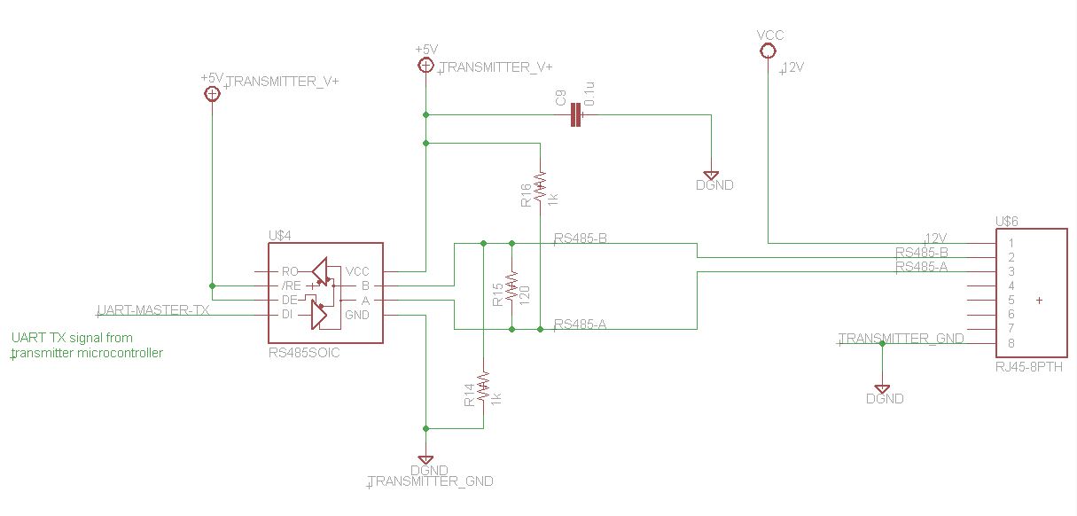
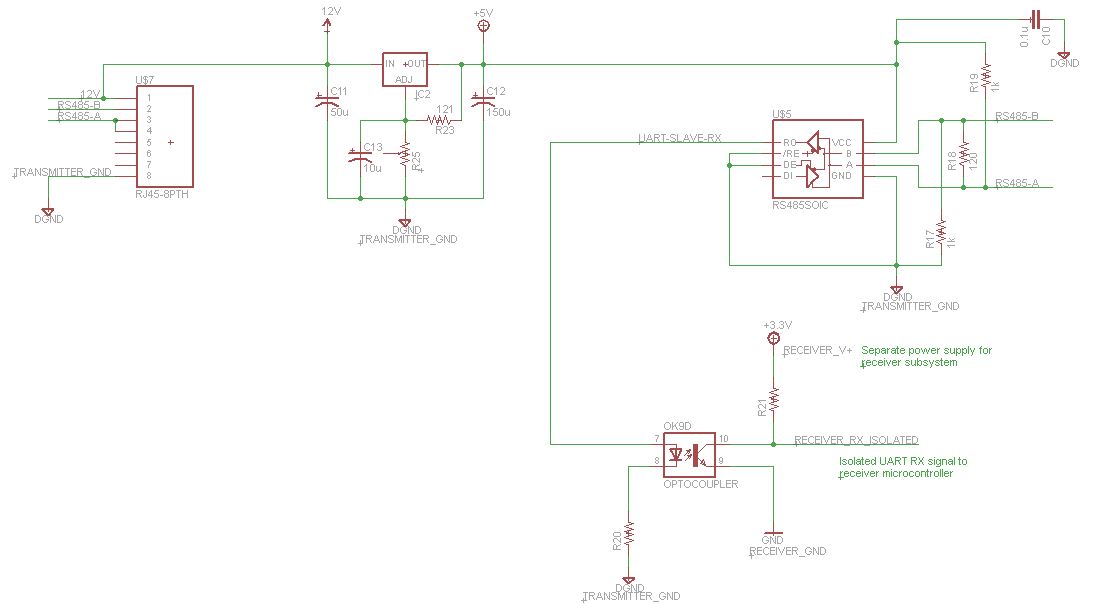
I have an application where a master/transmitter system communicates with a slave/receiver subsystem over an arbitrary distance. The two systems each consists of a microcontroller and some analog and digital circuitry. For communications between the two systems, a UART signal from the transmitter system is sent to a SN75176 differential bus transceiver to convert the UART signal to RS485. Similarly, on the receiver side, the RS485 signal is converted back to UART by another SN75176 for the receiver system's microcontroller to receive data/instructions from the transmitter system. A CAT-5e cable is used for this communication.

A particular requirement for the design is that the two systems are powered from completely separate power sources. Thus, the two systems' power interfaces may have nothing in common with one another (not even a shared ground). A proposed solution for this is to power both SN75176 ICs from the transmitter system's power supply and to optically isolate the final UART output at the receiver side. One of the wires in the CAT-5e cable can be used as a power supply line and another as the ground line for powering the receiver side's SN75176 IC. The idea is that the communications can be made to work while having two independent/isolated power supplies for the two systems. The following two circuit diagrams illustrate the setup.

For the transmitter system: Transmitter system circuit

For the receiver system: Receiver system circuit

From the SN75176's datasheet, the supply voltage must be between 4.75 V and 7 V (with 5-5.25 V being the ideal choice). Wikipedia indicates that CAT-5e cable has a resistance of 0.188 ohm/meter. If it is assumed that a max of 200 mA of current can flow in the cable (for the RS485 comms, receiver SN75176 power and optical isolation), then the voltage drop per meter of cable is:

$$ V_{drop} = I * R = (0.2 A)*(0.188 ohm) = 0.0376 [V/m]. $$

For a cable length of 80 m, the voltage drop is thus: $$ V_{drop} = (80 m)*(0.0376 V/m) = 3.008 V $$

If VCC in the transmitter circuit diagram is 12 V, then the power supply to the receiver SN75176 via the CAT-5e cable would be \$12 V - 3 V = 9 V\$, which would still be fine for the voltage regulator to regulate down to the suitable voltage level for the receiver SN75176 IC. By using the potentiometer (R25 in the receiver circuit), the output voltage of the regulator can be tuned to the desired supply voltage for the receiver SN75176 IC. The reason for using the voltage regulator, and not just a direct 5 V connection from the transmitter side to the receiver side's SN75176 power supply, is that the losses over the cable would drop the receiver side's SN75176 supply voltage to below the specified minimum. Conversely, a direct 12 V connection would provide a supply voltage that is too high.

The following questions now arise:

  1. Should the distance/length of the cable be much longer, the input voltage to the voltage regulator could drop to below the drop-out voltage of the regulator (due to losses over the long cable), rendering it unusable for supplying power to the receiver SN75176 IC. Could a higher input voltage (higher than 12 V as indicated in the schematic) solve this problem?
  2. Would the concept of optically isolating the UART RX signal at the receiver side be feasible?
  3. Is the concept of using the voltage regulator feasible?
  4. Would this setup work in the first place?

Is there any other method that would be better to use than the prescribed method?

\$\endgroup\$
1
  • 1
    \$\begingroup\$ Note that SN75176 is a legacy part (how many decades old now? 4?) that is much less robust than many of the newer parts that don't cost more. It's not fault-tolerant and is thus only reasonable for use on point-to-point links. Since you're using RS-485, you probably have multidrop applications in mind later. For those, SN75176 should be everyone's last choice. It is a source or endless problems in industrial networks that suffer from common-mode transients and other upsets. \$\endgroup\$ Commented Oct 27, 2021 at 19:46

2 Answers 2

2
\$\begingroup\$

Your concept is feasible, and will work.

A longer cable indeed might drop too much voltage. Simply increasing the voltage will work, but to reduce losses, it might be a better idea to use a switching regulator so that you can also use a lower current. (Power over Ethernet uses 48 V for this reason.)

An alternative to providing power over the cable would be using an isolated DC/DC supply at the receiver. (There are modules like the LTM2881 that integrate the RS-485 transceiver and the isolated power supply.)

\$\endgroup\$
1
  • \$\begingroup\$ Thank you for the suggestion of the LTM2881. Although rather expensive, it seems to have everything needed in one package. I will also look into isolated DC/DC converters, which might be a "cleaner" way of providing power to the receiver. \$\endgroup\$
    – wave.jaco
    Commented Nov 16, 2017 at 6:21
3
\$\begingroup\$

RS485 requires a ground. See here.

"Proper wiring[6]: RS-485 specifies differential transmission, which requires two signal wires in addition to a ground wire (commonly a 24AWG twisted pair) to transmit the signal. The two signal wires carry signals opposite in polarity, and greatly reduce the problems of radiated EMI and EMI pickup.

In the SN75176 datasheet you would not be able to guarantee the common mode signal levels if there was no earth/ground connection between the Rx/Tx pairs. If you are going to span more than a few hundred feet you may also find you earth potential will vary by several volts, so it's best to provide isolation to avoid this.

You may be better using a +/- 20 or 60 mA current loop providing your data transfer (baud rate) rate is modest.

\$\endgroup\$
3
  • 1
    \$\begingroup\$ The schematic does indicate a ground wire along with the RS-485 differential pair. It is labelled as "TRANSMITTER_GND". So I am using a ground wire. Thanks for the link, will read through it for some supplementary information. \$\endgroup\$
    – wave.jaco
    Commented Nov 9, 2017 at 0:10
  • \$\begingroup\$ @wave.jaco ....the comment on ground was because in your question you quoted " Thus, the two systems' power interfaces may have nothing in common with one another (not even a shared ground)." .....and for RS485 you MUST have a shared ground. \$\endgroup\$ Commented Nov 9, 2017 at 0:52
  • \$\begingroup\$ My apologies for the misunderstanding. I understand that RS485 needs a common ground signal to work. The idea was that the receiver side SN75176 still use the same ground as the transmitter side, but that from the receiver UART RX signal it works on another power supply. That is why I want to optically isolate the UART signal at the receiver side. \$\endgroup\$
    – wave.jaco
    Commented Nov 9, 2017 at 5:18

Your Answer

By clicking “Post Your Answer”, you agree to our terms of service and acknowledge you have read our privacy policy.

Not the answer you're looking for? Browse other questions tagged or ask your own question.