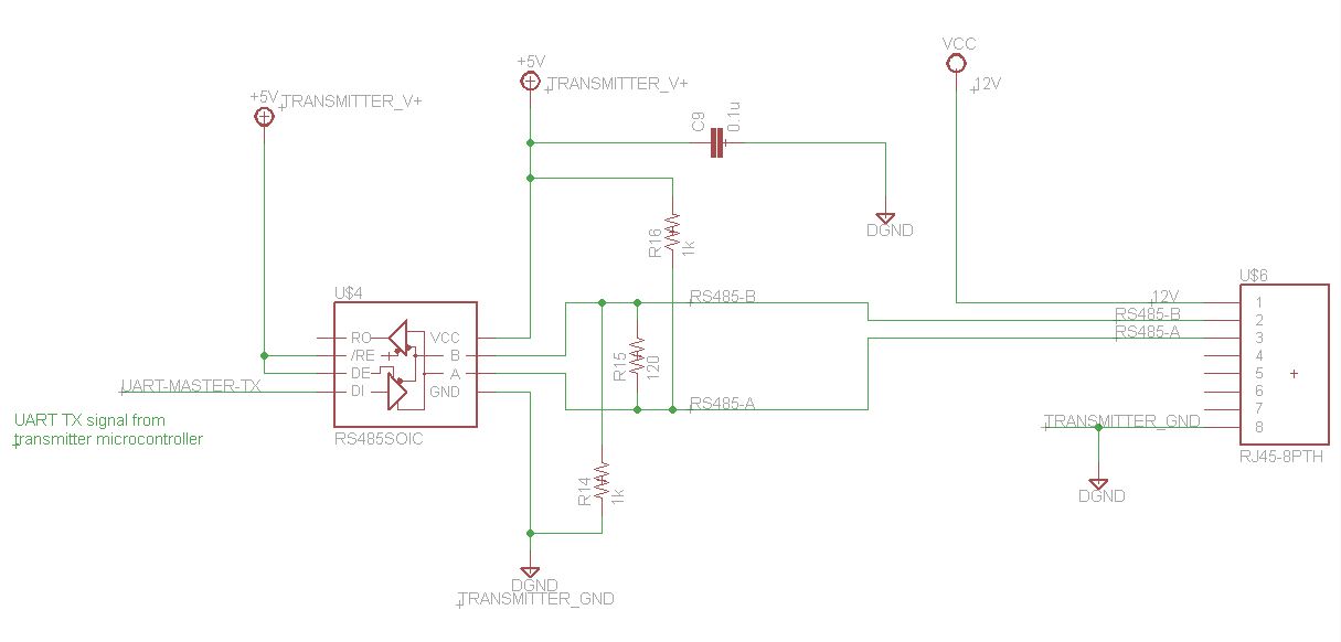
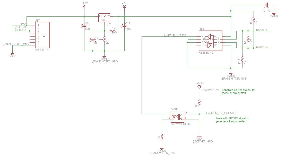
I have an application where a master/transmitter system communicates with a slave/receiver subsystem over an arbitrary distance. The two systems each consists of a microcontroller and some analog and digital circuitry. For communications between the two systems, a UART signal from the transmitter system is sent to a SN75176 differential bus transceiver to convert the UART signal to RS485. Similarly, on the receiver side, the RS485 signal is converted back to UART by another SN75176 for the receiver system's microcontroller to receive data/instructions from the transmitter system. A CAT-5e cable is used for this communication.
A particular requirement for the design is that the two systems are powered from completely separate power sources. Thus, the two systems' power interfaces may have nothing in common with one another (not even a shared ground). A proposed solution for this is to power both SN75176 ICs from the transmitter system's power supply and to optically isolate the final UART output at the receiver side. One of the wires in the CAT-5e cable can be used as a power supply line and another as the ground line for powering the receiver side's SN75176 IC. The idea is that the communications can be made to work while having two independent/isolated power supplies for the two systems. The following two circuit diagrams illustrate the setup.
From the SN75176's datasheet, the supply voltage must be between 4.75 V and 7 V (with 5-5.25 V being the ideal choice). Wikipedia indicates that CAT-5e cable has a resistance of 0.188 ohm/meter. If it is assumed that a max of 200 mA of current can flow in the cable (for the RS485 comms, receiver SN75176 power and optical isolation), then the voltage drop per meter of cable is:
$$ V_{drop} = I * R = (0.2 A)*(0.188 ohm) = 0.0376 [V/m]. $$
For a cable length of 80 m, the voltage drop is thus: $$ V_{drop} = (80 m)*(0.0376 V/m) = 3.008 V $$
If VCC in the transmitter circuit diagram is 12 V, then the power supply to the receiver SN75176 via the CAT-5e cable would be \$12 V - 3 V = 9 V\$, which would still be fine for the voltage regulator to regulate down to the suitable voltage level for the receiver SN75176 IC. By using the potentiometer (R25 in the receiver circuit), the output voltage of the regulator can be tuned to the desired supply voltage for the receiver SN75176 IC. The reason for using the voltage regulator, and not just a direct 5 V connection from the transmitter side to the receiver side's SN75176 power supply, is that the losses over the cable would drop the receiver side's SN75176 supply voltage to below the specified minimum. Conversely, a direct 12 V connection would provide a supply voltage that is too high.
The following questions now arise:
- Should the distance/length of the cable be much longer, the input voltage to the voltage regulator could drop to below the drop-out voltage of the regulator (due to losses over the long cable), rendering it unusable for supplying power to the receiver SN75176 IC. Could a higher input voltage (higher than 12 V as indicated in the schematic) solve this problem?
- Would the concept of optically isolating the UART RX signal at the receiver side be feasible?
- Is the concept of using the voltage regulator feasible?
- Would this setup work in the first place?
Is there any other method that would be better to use than the prescribed method?


