0
\$\begingroup\$

My question is, how can I control multiple tiny PWM capable controllers, like this https://www.sparkfun.com/products/retired/8897, with one "master" MCU for the purpose of controlling LED arrays?

This is where I came upon the idea: Microcontroller with lots of PWM outputs

I'm an aspiring biologist attempting to construct an LED device which I can use for photosynthesis research. The device will be a series of containers with LEDs embedded in the lids. It's based off of this paper.

They don't provide much in the way of a how to, so I'm attempting to sort of reverse engineer the device.

Individual LEDs are typically somewhat variable in wavelength and intensity output at a given current. I will be testing the wavelength and intensity outputs for each diode and each array and adjusting the PWM and possibly the current in order to have several containers all with lids producing the same, or close to, spectral power distribution and total light intensity. My thought is to have one of the tiny controllers in each container lid and a master arduino or other such MCU to which I can upload any changes in spectrum or intensity I'd like to make. This seems like a great setup due to the flexibility of being able to add additional lids/tiny controllers and being able to change the spectrum and intensity for future experiments.

\$\endgroup\$
2
  • \$\begingroup\$ How critical is the color spectrum of the LEDs? Or are you just considering RGB LEDs? If so you could look into "addressable" LEDs (WS2812, APA102, etc). \$\endgroup\$
    – Wesley Lee
    Commented Nov 9, 2017 at 21:10
  • 1
    \$\begingroup\$ The B7 timer of the MSP430 gives you SEVEN counter timers all tied to a single clock chain/counter with PWM capability. And that's just a tiny, cheap, widely available, lower power chip. But I also think you may need to hire someone to help you think through your project. LED temperature also affects wavelength and intensity, for example. And there are many other factors you may want to place under control, or else compensate for, in some fashion. You need to sit down and talk with someone who can interact with you and work out a plan that has a high chance of success. IMHO. \$\endgroup\$
    – jonk
    Commented Nov 9, 2017 at 22:09

3 Answers 3

1
\$\begingroup\$

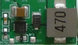
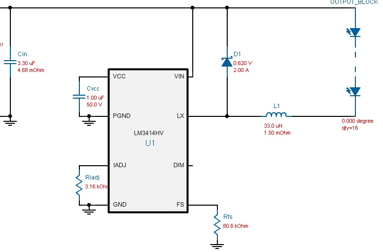
I would put buck LED drivers in the lid. Driving strings of 16 LEDs using a power supply of 48V.

enter image description here

enter image description here


For the LEDs I'd use:

  • White and deep blue: Cree XP-3G
  • Red, deep red, far red: OSRAM SSL 150

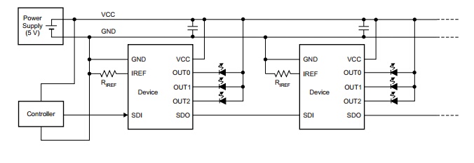
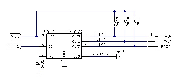
Use a TI TLC5973 3-Channel, 12-Bit, PWM Constant-Current LED Driver with Single-Wire Interface.

enter image description here


But rather than driving LEDs, use the outputs to drive the DIM pin of the buck driver.

enter image description here

\$\endgroup\$
0
\$\begingroup\$

There are dimmer controllers made specifically for LEDs. Have a look at PCA9532 and PCA9536 for an example. These are controlled through I2C bus. They have 3 address bits, which allows to control 8 of them with one I2C bus.

p.s.
You need to write down more fundamental aspects of your experimental setup such as: desired light output, wavelengths, models of LEDs, number of LEDs, should you use PWM or linear control. Digital control is nice and convenient, but I wouldn't be too concerned about that at an early stage of the experiment design that you are currently at.

\$\endgroup\$
0
\$\begingroup\$

As far as LED controllers, there are many multi-port drivers with PWM depending on input serial or parallel and output current range.

e.g. 6 port 200mA per port

https://www.digikey.com/product-detail/en/texas-instruments/TPS61196PWPR/296-40824-2-ND/3880034

\$\endgroup\$

Your Answer

By clicking “Post Your Answer”, you agree to our terms of service and acknowledge you have read our privacy policy.

Not the answer you're looking for? Browse other questions tagged or ask your own question.