5
\$\begingroup\$

I am trying to design a charging circuit for a lithium polymer battery with 2200 mAh capacity and 3.7 V nominal voltage. The integrated circuit for the control of the charge of the battery is the MCP73831 and as a power supply a solar panel of 6.2 Voc and Isc =175 mA is used (I do not have more information about the solar panel). The atmega328p is used as a microcontroller. On the one hand, I want to detect the three states of the tri-state output (pin 1 MCP73831). For this, I used the solution proposed in (How can I read a tristate output with microcontroller? by @Wouter van Ooijen), with the voltage divider connect to microcontroller ADC but I would also like to add a LED connected to pin 1 (STAT) so that it only lights when STAT is a low (not in high impedance). I mainly have two questions (if you see any more mistakes or improvements, I would appreciate it if you told me).

  1. I have put a zener diode (BZT52H-C5V6) with a Vz = 6 V to ensure that the maximum voltage allowed on pin 4 (MCP73831) is not exceeded. It is right? It is not necessary?
  2. Would both the led (TLMS1000 red) and the voltage divider work to detect the three states?

schematic

simulate this circuit – Schematic created using CircuitLab

Thanks in advance. Best regards.

\$\endgroup\$
2
  • \$\begingroup\$ Sorry, but... I don't see the microcontroller. Where is it? What is it connected to? you connected the solar panel to stat, and then to VDD through a 150k resistor. I think you made some errors in the schematic when you ported it here... \$\endgroup\$
    – frarugi87
    Commented Nov 17, 2017 at 12:50
  • \$\begingroup\$ sorry, I am going to edit the circuit \$\endgroup\$ Commented Nov 17, 2017 at 12:59

3 Answers 3

2
\$\begingroup\$

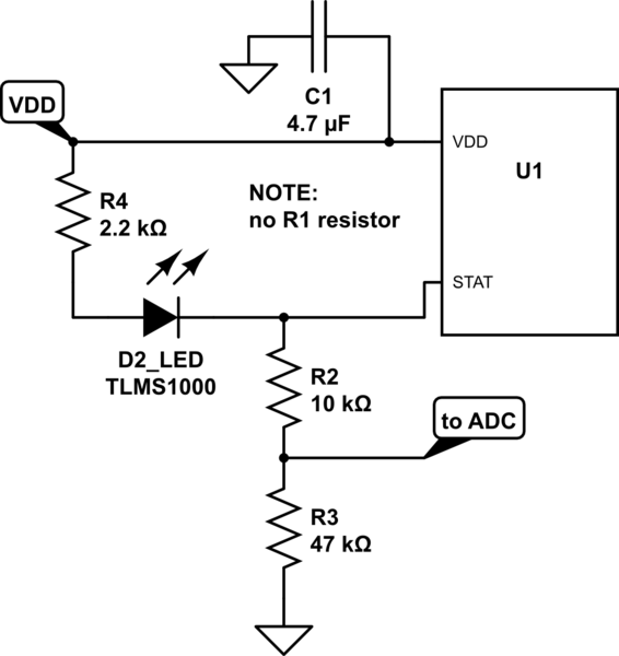
From what I read (but I never used those ICs) if the open circuit voltage is 6.2V you can omit the 6V zener. In fact, the voltage at its output decreases with the load, and the maximum rating of the IC is 7V, so up to 7V it should not break. You can test it, or wait for someone more expert than me to come and say that I am completely wrong (but I hope I'm not).

As for the microcontroller and LED, your circuit is ok for the LED (it will light only when STAT is tied low), but I don't think the uC will like it. When STAT is tied to VCC the voltage can reach 6V, while usually the uC can bear Vcc+0.3V on their pins (so 5.3V if it is 5V powered or 3.6V if it is 3.3V powered). I suggest you modify your circuit in

schematic

simulate this circuit – Schematic created using CircuitLab

I refer to the graph in figure 13 and 14 in the TLMS1000 datasheet. The scheme, with a VDD of 6V, provides you these data:

  • STAT = VDD:
    • voltage at STAT PIN = 6V
    • voltage on the whole LED branch = 0, current in LED = 0, luminosity = 0
    • voltage on ADC is 47/57*6V = 4.95V
  • STAT = GND:
    • voltage at STAT PIN = 0V
    • voltage on the whole LED branch = 6V, current in LED = 2mA, luminosity = 100% of specified luminosity
    • voltage on ADC is 0V
  • STAT = HI-Z:
    • if we estimate a current around 50uA-100uA, the voltage on the LED is not in the graph (the graph goes as low as 100uA). In any case, I expect it to be roughly around 1.5V-1.6V)
    • if the voltage on the LED is 1.5V, the current in the branch is (6-1.5)/(2.2+10+47) = 75uA. The luminosity of the LED is around 2-3% of the nominal luminosity (cannot be seen)
    • voltage on ADC is 47*75uA = 3.53V

If you have a 3.3V microcontroller, to keep almost the same values you can substitute the 10k and 47k resistors with, respectively, a 27k and 33k one. This way the LED will see the same circuit, while on the ADC

  • STAT = VDD: voltage on ADC is 33/60*6V = 3.3V
  • STAT = GND: voltage on ADC is 0V
  • STAT = HI-Z: voltage on ADC is 33*75uA = 2.48V
\$\endgroup\$
1
  • \$\begingroup\$ Sorry for the delay. Thanks for such a detailed response and all the corrections. I'll wait a bit before validating your answer in case there is a correction. \$\endgroup\$ Commented Nov 19, 2017 at 20:03
1
\$\begingroup\$

I have a comment on the charging chip directly connected to the solar panel output. I would put a buck-boost converter that is designed for maximum power point tracking (MPPT) like this ST SPV1050. The IV curve will be very different than you may suspect. Both Isc and Voc will not be realistic, you can see another discussion mention the solar power curve. It may work directly if the panel is in full sun and power isn't limited, but the efficiency will not be optimized.

1) If you use this charger, the zener diode is unnecessary, the MCP73831 has an absolute max of 7.0V for the input and the panel you mention has a Voc of 6.2V.

2) The voltage divide circuit is unnecessary. The STAT pin can use a LED (for both high and low), the way you've set it will light when the pin is low (however I would reduce the resistor to 330 - 680 ohm to make sure it's visible). Rather than an ADC, the STAT pin can be tracked by a micro with a simple GPIO input.

\$\endgroup\$
3
  • \$\begingroup\$ As Frarugi mentioned, the STAT pin could be outside the micro pin range. I would add some sort of buffer to translate high vs low output from the STAT pin. \$\endgroup\$ Commented Nov 17, 2017 at 14:47
  • \$\begingroup\$ Thank you for your answer and your comment on the solar panel. I did not know about the existence of the buck-boost converter. These IC, what do they really do? Do they try to do work to the solar panel work at a work point to extract maximum power? With the MCP73831, would not it work? I'm considering using the BQ24210 (ti.com/lit/ds/symlink/bq24210.pdf)¿do you see it right? I have no experience with solar panels and very little experience in electronic design. Thanks again. \$\endgroup\$ Commented Nov 19, 2017 at 20:18
  • \$\begingroup\$ @critically-damped using a buffer or in any case using a GPIO you will lose the three state detectability (you will either sense high or low, not the hi-z state), unless you use two pins (one connected to a resistor and used as output, to pull up or down the line, and the other to sense) \$\endgroup\$
    – frarugi87
    Commented Nov 20, 2017 at 8:40
0
\$\begingroup\$

I also am using the MCP73831 and wanted to connect STAT to 3.3v MCU.

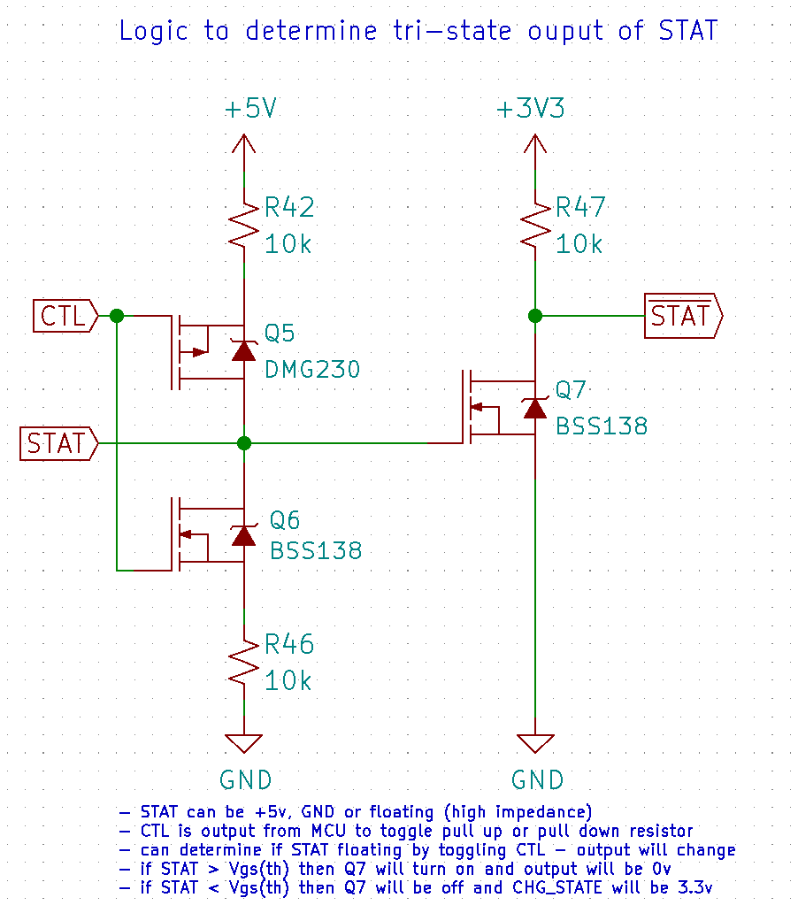
As an alternative to the voltage divider that others have suggested, I used a second GPIO pin of the MCU to toggle a pull-up (R42) / pulldown (R46) resistor using a P-Channel (Q5) and N-channel (Q6) MOSFET (see circuit below). I then took STAT and put it through a simple inverter to make sure the output is between 0v and 3.3v.

Note: Weaker Pull-up and pulldown resistors could probably be used to even further reduce current usage.

For this to work, the MCU would then need to take 2 readings, the first with CTL low and the second with CTL high. If the readings change, then ~STAT must be floating.

Hope this helps everyone.

enter image description here

\$\endgroup\$
2
  • \$\begingroup\$ By now you have posted three answers and all are the same! I will flag this as spam, because you keep describing your circuit again and again. \$\endgroup\$
    – jusaca
    Commented Jun 30, 2020 at 7:31
  • \$\begingroup\$ apologies... I was responding to 3 different questions, so wanted to post the answer to them all independently. I was just trying to help... Sorry if you saw this as spam. \$\endgroup\$
    – Doug Inman
    Commented Jun 30, 2020 at 7:45

Your Answer

By clicking “Post Your Answer”, you agree to our terms of service and acknowledge you have read our privacy policy.

Not the answer you're looking for? Browse other questions tagged or ask your own question.