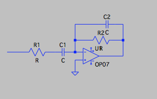
So I have found the circuit for a band pass filter. I know its function and what it does, but I haven't understood yet why its components are placed were they are. Why are the capacitors and the resistors formed this way? and how their placement affects the form my voltage graph will have (square to sin graph) 
-
\$\begingroup\$ This filter is a combination of 2 RC filters and an opamp based amplifier. You need to understand those type of circuits first before you can understand this one. For RC filters, read: en.wikipedia.org/wiki/RC_circuit For opamp based amplifiers read: en.wikipedia.org/wiki/Operational_amplifier_applications \$\endgroup\$– BimpelrekkieCommented Nov 28, 2017 at 21:46
2 Answers
This configuration is an active inverting bandpass filter. Simply said, low frequencies are blocked by capacitor C1 while capacitor C2 enables high frequencies to pass through untouched. Both cutoff frequencies (frequency at which the amplitude reaches -3dB) are adjustable independently.
Low pass filter cutoff frequency is set by R2 and C2.
\begin{equation} f_L = \frac{1}{2 \pi R_2 C_2} \end{equation}
High pass filter cutoff frequency is set by R1 and C1
\begin{equation} f_H = \frac{1}{2 \pi R_1 C_1} \end{equation}
Setting \$ f_H < f_L \$, pass-band voltage gain is approximated by resistor ratio.
\begin{equation} A_v \approx \frac{-R_2}{R_1} \end{equation}
A square wave passed through this filter will be a sum of sine waves. All frequencies in the pass-band will be kept untouched, while other will see their amplitude reduced and phase altered.
-
\$\begingroup\$ I try to imagine filters , a large ice cube to an ice statue we want , so when the square wave will pass in the filter , the filter will slice some parts and modify the others to make it a sine wave. What I don't understand is what role do the capacitors play? how does the capacitor C1 blocks the low frequencies and how does C2 enables high frequencies? And last but not least what role does the op amp play? why not use the RC circuits alone? \$\endgroup\$– user170589Commented Nov 28, 2017 at 22:14
-
2\$\begingroup\$ @Maverick98 Do you understand the concept of capacitive reactance? It is that reactance that is interacting with the resistors to create the filtering action. Capacitive reactance increases as the frequency decreases so that C1 blocks low frequencies. Capactive reactance decreases as the frequency increases so that C2 passes high frequencies. If you don't understand this, then I suggest you study the electrical properties of capacitors before trying to understand simple RC high and low pass filters. \$\endgroup\$– BarryCommented Nov 29, 2017 at 0:34
-
\$\begingroup\$ No - the answer from altai is NOT CORRECT. We are not allowed to separately consider both RC networks. It is not a problem to find the transfer function and the midband gain Ao=R2C1/(R1C1+R2C2). \$\endgroup\$– LvWCommented Nov 29, 2017 at 9:12
-
\$\begingroup\$ The general transfer function is H(s)=sR2C1/[1+s(R1C1+R2C2)+s²(R1R2C1C2)] \$\endgroup\$– LvWCommented Nov 29, 2017 at 9:21
-
\$\begingroup\$ @LvW Simply find the roots of the denominator's polynomial and you'll see exactly why we can consider both RC seperately. We have s1 = -1/(C1R1) and s2 = -1/(C2R2). Also, assuming f_L < f_H, we can simplify the gain to -R2C1/R1C1 = -R2/R1, as stated in my original answer. \$\endgroup\$– altaiCommented Nov 29, 2017 at 14:19
It may help to think about the circuit in two parts.
Input

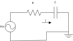
In the first half, we have the input signal running through a resistor and capacitor in series. Recalling that capacitors "block" current at low frequency and "pass" current at higher frequencies, inituitively we can say that this part screens low frequency signals. Lets say it effectively screens upto some frequency \$f_1\$.
Output
![Second Half of Circuit[2]](https://i.sstatic.net/H0wdw.png)
In the second part of the circuit, we have a resistor and capacitor in parallel. Keeping in mind the properties of capacitors, at lower frequencies the current will mostly be flowing through the resistor. At some frequency, \$f_2\$, the capacitor will start allowing more and more current through it; effectively shorting the resistor out.
Applying the golden rule of op-amps, once the resistor has been shorted out, the op-amp has acheived its goal of \$V_{invert} = V_{non-invert}\$ and will try and do whatever it can to maintain that.
To make a bandpass filter, we must choose the frequency setting of each half such that \$f_1 < f_2\$. altai's answer provides the specifics.
Active Filters
There are several reasons to use an op-amp in a filter. One reason is it allows the circuit to have gain during the pass-band.
More information can be found here.
-
\$\begingroup\$ No - it is NOT CORRECT to require f1<f2. You must not consider each RC branch separately. As an example: For R1=R2=R and C1=C2=C the transfer function of the bandpass is H(s)=sRC/(1+2sRC+s²R²C²) \$\endgroup\$– LvWCommented Nov 29, 2017 at 9:15
