1
\$\begingroup\$

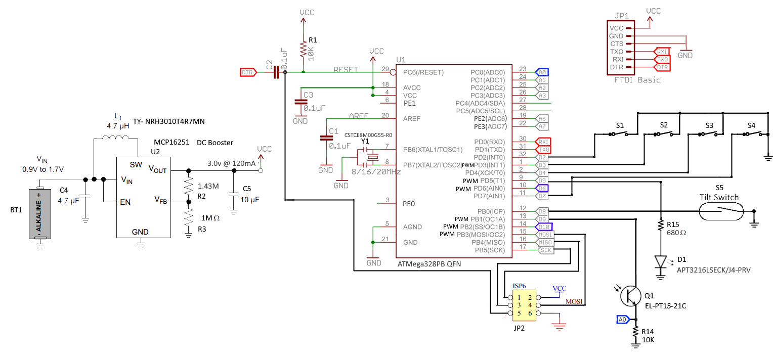
Because I am a software dude, I would like some help verifying this minimal Arduino based circuit which I designed with some changes.

It is single AAA cell operated (NiCd or Alkaline), needs to be very energy efficient. Both ATMega and the DC Booster can be configured to any voltage between +1.8v to +5.5v, so I can go higher than +2.2v. Input: 4 push buttons, each can wake it up from sleep using Pin Change Interrupt on port D (All switches are pulled up internally). Once awake the circuit should read which switch woke it, A visible light Phototransistor whose analog value can be read. A tact switch whose on/off value can be read (pulled up internally). Output is done by blinking an LED using PWM. The software (including Arduino boot loader) needs to be burned over SPI using USBTinyISP. The FTDI port is for Arduino IDE debugging.

Are there errors in the attached design? Anything missing? Anything can be improved? enter image description here

I ultimately built the circuit, and now have a problem with serial communication as described in this link.

\$\endgroup\$
7
  • 1
    \$\begingroup\$ You seem to like pull-down resistors. Any good reason to prefer them opver the built-in pull-up resistors? And what is the purpose of C2 when you program over the ICSP? \$\endgroup\$ Commented Dec 2, 2017 at 9:48
  • \$\begingroup\$ With only 0.2V headroom for the resistor the current through the LED is not very well controlled. You could switch LED and resistor, and semse the voltage over the resistor with an A/D input. This way you can PWM when the LED current is higher than you aimed for. \$\endgroup\$ Commented Dec 2, 2017 at 9:52
  • \$\begingroup\$ Can the light sensor also wake the chip up? If that is the case I don't see why it is powered from a GPIO. \$\endgroup\$ Commented Dec 2, 2017 at 9:53
  • \$\begingroup\$ Wouter, I changed to the internal pull ups. C2 I copied from a reference design I saw. Don't know what its for.The light sensor can't wake the chip. It is powered from GPIO because most of the time when the chip is awake it is not needed, so I want it to draw current only when a reading is needed. \$\endgroup\$
    – Gary
    Commented Dec 2, 2017 at 12:15
  • \$\begingroup\$ What minimal Vcc value will be high enough for this LED? Alternatively, will a 1.75v LED do much better under 2.2v Vcc? \$\endgroup\$
    – Gary
    Commented Dec 2, 2017 at 12:24

3 Answers 3

0
\$\begingroup\$

When you say "Arduino," do you mean hardware compatible, software (library) compatible, or boot-loader compatible? Based on your description and circuit, I assume the latter two.

Microcontroller

The ATmega328p (datasheet) is a great MCU. It was a good choice for the basic Arduino circuits. The speed grade is

0 - [email protected] - 5.5V, 0 - [email protected] - 5.5.V, 0 - 20MHz @ 4.5 - 5.5V

so you have those frequency limitations. You don't specify what the actual resonator frequency is in the schematic (looks like a resonator with built in capacitors, rather than a crystal with external caps). AFAIK, Arduino libraries expects a 16MHz CPU frequency to work as expected. It will not (reliably) operate at that frequency with < 4.5V VCC.

On that note, this is a virgin chip I presume (direct from distributor, no pre-installed firmware). So it will have the default fuse settings (8MHz internal Osc with /8 option so F_CPU = 1MHz). Also, for bootloaders, the "Boot reset vector" fuse should be enabled so the chip boots into the bootloader part of memory. This website is the De Facto standard fuse calculator.

I'm not the most familiar with Arduino. I think the bootloader is using the serial DTR signal in combination with C2 to reset the device from the bootloader so you don't have to manually press reset. Speaking of which, are you sure you don't want a physical reset button on board?

Also, if you plan to use the SPI bus for anything else but ISP, you will need to put resistors (330 ohm) in line with MISO, MOSI, and SCK so the programmer stays happy. See this app note AVR 042 - it has a lot of great hardware design guides for AVR.

Pull Resistors

It's typically not a good idea to directly connect a pin to a voltage level in case that pin were to be set and shorted - better to use an in line resistor. As Wouter pointed out, this MCU (and most, for that matter) have internal pull-up resistors, so your button inputs would to better to just connect to ground through a strong resistor. This would mean your inputs are "active low." It's common to do this.
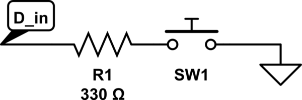
schematic

simulate this circuit – Schematic created using CircuitLab

This setup will also reduce power consumption when your buttons are pressed because the internal pull-up will be 20k - 50k ohms. Additionally, it reduces the number of PCB traces to those switches, so cheaper/easier fabrication.

FTDI

Is this going to a USB jack (not in the schematic)? Are you sure your FTDI can work with UART signals in the 2.2V range? Will the VCC line be powering the chip or is it powered from the USB? If it's USB, that's 5V coming in to dominate your VCC bus (unless you don't connect that pin)!

LED Output

The LED (datasheet) wants to drop 2V with a forward current of 5mA. If you're pulsing this (PWM), you can overdrive it. Also mentioned by Wouter, your series resistor will only have 0.2V to drop. (VCC - V_LED). The LED current will be 0.2 / 20Ohms = 10mA (when the pulse is high). Of course, it will probably drop more than 2V at this current (don't see a V-I plot to know for sure), so it's hard to say what the LED voltage/current will actually be. The Mega328p source 40mA per pin (200mA total through VCC, 150mA total in the PORTS) - although Arduino ignores PORT configurations in favor of ... "simplicity"). The maximum current from an IO pin at VCC = 3V is 10mA. You might not be able to drive the LED with this much current for your power setup. This LED is connected to PD5, which can also be the output for Timer 0 compare match B to have hardware-controlled PWM.

Light Sensor

I presume you are powering this from a chip output pin so you can turn it off and on to save power? Also, with AVCC being powered from a switching regulator, there will be a lot of noise in the ADC. This is fine if this measurement doesn't need to be extremely precise. I'd suggest setting it up for 8-bit resolution and averaging over 8/16 samples (best to do things in powers of 2 for optimized division with bit-shifts).

Tilt Switch

I presume this is a digital input? I'd suggest moving it to PORT D with your other digital inputs. It will simplify the code, especially if you don't use the dreadful Arduino handling of pins or if you ever want it to be an external wake-up source as well.
\$\endgroup\$
2
  • \$\begingroup\$ Kurt Thanks so much for the elaborate answer. Did a lot of reading on fuses etc. Indeed bootloader and library compatibility. I read Arduino libs work with 8Mhz. So I would change osc' to 8Mhz CSTCE8M00G55-R0 (8Mhz is enough for me). mouser.co.il/ProductDetail/Murata-Electronics/CSTCE8M00G55-R0/… And raise booster to 3v which is good for 8Mhz and for the LED. Booster would still give >100mA which is enough for my app. I will also change to a 1.75 LED to increase res' drop to 1.25 (Vcc == 3.0). \$\endgroup\$
    – Gary
    Commented Dec 3, 2017 at 20:42
  • \$\begingroup\$ Regarding FTDI, I thought to use USB-FTDI card and disconnect the battery when programming via SPI or via FTDI. Will the voltages be OK with that? Indeed the light sensor is driven from output pin to save power when not in use. The measurement does not need be accurate. I'll average as you suggest. I'd never want the tilt switch to wake up the system, but how would moving it to port D simplify coding? I don't have reset button because for user experience I need to wake up only from the push buttons. Once I clean all SW bugs, is there a reason why hard reset might be needed? \$\endgroup\$
    – Gary
    Commented Dec 3, 2017 at 20:43
1
\$\begingroup\$

A comment has no decent formatting, hence an answer.

I would consider 0.2V headroom for a LED resistor too low. I would either

  1. select a LED with a lower drop voltage, 1.75V more than doubles the resistor drop and hence the current stability

  2. design the current to be far below the maximum (and far above what is needed for visibility)

  3. measure the current (A/D) and apply PWM to get the desired average LED current.

\$\endgroup\$
0
\$\begingroup\$

I'd put a 0.1uF cap on EACH power pin, it's ground as close as possible to the appropriate power pin's ground.

I suspect you may also need a 0.1uF cap to ground on your reset line for power on reset

\$\endgroup\$

Your Answer

By clicking “Post Your Answer”, you agree to our terms of service and acknowledge you have read our privacy policy.

Not the answer you're looking for? Browse other questions tagged or ask your own question.