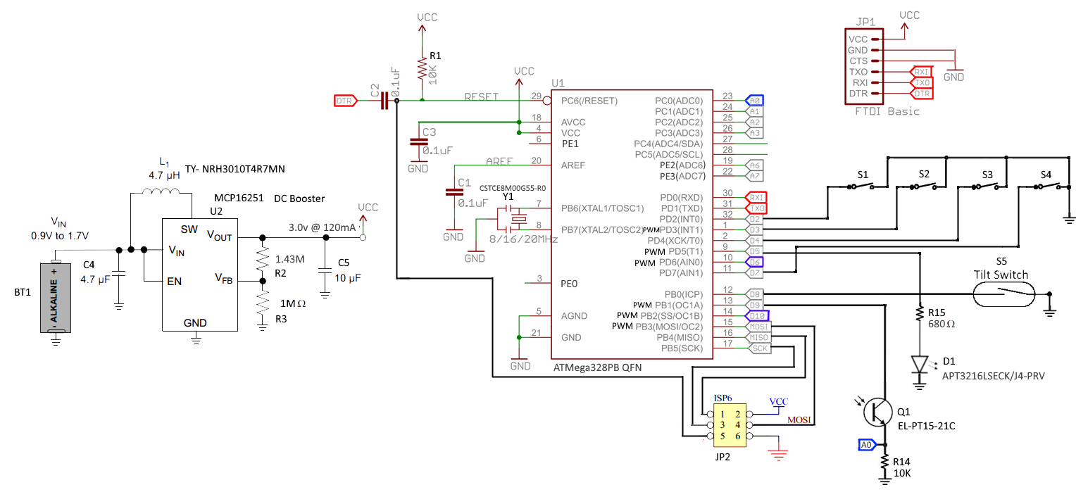
When you say "Arduino," do you mean hardware compatible, software (library) compatible, or boot-loader compatible? Based on your description and circuit, I assume the latter two.
Microcontroller
The ATmega328p (datasheet) is a great MCU. It was a good choice for the basic Arduino circuits. The speed grade is
0 - [email protected] - 5.5V, 0 - [email protected] - 5.5.V, 0 - 20MHz @ 4.5 - 5.5V
so you have those frequency limitations. You don't specify what the actual resonator frequency is in the schematic (looks like a resonator with built in capacitors, rather than a crystal with external caps). AFAIK, Arduino libraries expects a 16MHz CPU frequency to work as expected. It will not (reliably) operate at that frequency with < 4.5V VCC.
On that note, this is a virgin chip I presume (direct from distributor, no pre-installed firmware). So it will have the default fuse settings (8MHz internal Osc with /8 option so F_CPU = 1MHz). Also, for bootloaders, the "Boot reset vector" fuse should be enabled so the chip boots into the bootloader part of memory. This website is the De Facto standard fuse calculator.
I'm not the most familiar with Arduino. I think the bootloader is using the serial DTR signal in combination with C2 to reset the device from the bootloader so you don't have to manually press reset. Speaking of which, are you sure you don't want a physical reset button on board?
Also, if you plan to use the SPI bus for anything else but ISP, you will need to put resistors (330 ohm) in line with MISO, MOSI, and SCK so the programmer stays happy. See this app note AVR 042 - it has a lot of great hardware design guides for AVR.
Pull Resistors
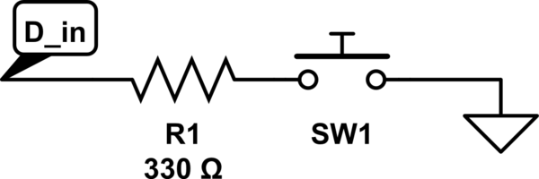
It's typically not a good idea to directly connect a pin to a voltage level in case that pin were to be set and shorted - better to use an in line resistor. As Wouter pointed out, this MCU (and most, for that matter) have internal pull-up resistors, so your button inputs would to better to just connect to ground through a strong resistor. This would mean your inputs are "active low." It's common to do this.

simulate this circuit – Schematic created using CircuitLab
This setup will also reduce power consumption when your buttons are pressed because the internal pull-up will be 20k - 50k ohms. Additionally, it reduces the number of PCB traces to those switches, so cheaper/easier fabrication.
FTDI
Is this going to a USB jack (not in the schematic)? Are you sure your FTDI can work with UART signals in the 2.2V range? Will the VCC line be powering the chip or is it powered from the USB? If it's USB, that's 5V coming in to dominate your VCC bus (unless you don't connect that pin)!
LED Output
The LED (datasheet) wants to drop 2V with a forward current of 5mA. If you're pulsing this (PWM), you can overdrive it. Also mentioned by Wouter, your series resistor will only have 0.2V to drop. (VCC - V_LED). The LED current will be 0.2 / 20Ohms = 10mA (when the pulse is high). Of course, it will probably drop more than 2V at this current (don't see a V-I plot to know for sure), so it's hard to say what the LED voltage/current will actually be. The Mega328p source 40mA per pin (200mA total through VCC, 150mA total in the PORTS) - although Arduino ignores PORT configurations in favor of ... "simplicity"). The maximum current from an IO pin at VCC = 3V is 10mA. You might not be able to drive the LED with this much current for your power setup. This LED is connected to PD5, which can also be the output for Timer 0 compare match B to have hardware-controlled PWM.
Light Sensor
I presume you are powering this from a chip output pin so you can turn it off and on to save power? Also, with AVCC being powered from a switching regulator, there will be a lot of noise in the ADC. This is fine if this measurement doesn't need to be extremely precise. I'd suggest setting it up for 8-bit resolution and averaging over 8/16 samples (best to do things in powers of 2 for optimized division with bit-shifts).
Tilt Switch
I presume this is a digital input? I'd suggest moving it to PORT D with your other digital inputs. It will simplify the code, especially if you don't use the dreadful Arduino handling of pins or if you ever want it to be an external wake-up source as well.


