I would like to ask some questions about inferring the priority and normal encoder using Verilog on the FPGA.
I've used the example codes from the book "advanced chip design practical examples in Verilog"
Code for pri_encoder
module pri_encoder
(D0, D1, D2, D3, D4, D5, D6, D7,
Q2Q1Q0);

input D0, D1, D2, D3, D4, D5, D6, D7;
output [2:0] Q2Q1Q0;
reg    [2:0] Q2Q1Q0;

always @*
  begin
    Q2Q1Q0 = 3'b000;
      if(D0) Q2Q1Q0 = 3'b000;
      else if(D1) Q2Q1Q0 = 3'b001;
      else if(D2) Q2Q1Q0 = 3'b010;
      else if(D3) Q2Q1Q0 = 3'b011;
      else if(D4) Q2Q1Q0 = 3'b100;
      else if(D5) Q2Q1Q0 = 3'b101;
      else if(D6) Q2Q1Q0 = 3'b110;
      else if(D7) Q2Q1Q0 = 3'b111;
  end
endmodule
Code for normal encoder
module encoder
(D0, D1, D2, D3, D4, D5, D6, D7,
Q2Q1Q0);

input D0, D1, D2, D3, D4, D5, D6, D7;
output [2:0] Q2Q1Q0;
reg    [2:0] Q2Q1Q0;

always @*
  begin
    Q2Q1Q0 = 3'b000;
    case (1'b1)
      D0: Q2Q1Q0 = 3'b000;
      D1: Q2Q1Q0 = 3'b001;
      D2: Q2Q1Q0 = 3'b010;
      D3: Q2Q1Q0 = 3'b011;
      D4: Q2Q1Q0 = 3'b100;
      D5: Q2Q1Q0 = 3'b101;
      D6: Q2Q1Q0 = 3'b110;
      D7: Q2Q1Q0 = 3'b111;
    endcase
  end
endmodule
The first question is about the constant expression in the switch case. It seems that constant expression can be located inside the switch (exp) and the element that has 1'b1 can be picked. Does it infer the priority encoder or just normal encoder?
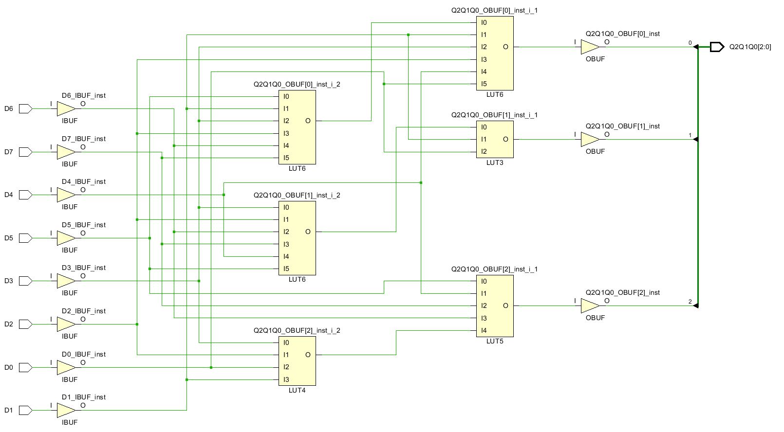
At the first glance, it seems like the case with constant expression will work like a priority encoder, but when I synthesize the above code on the Vivado platform, the synthesized schematic seems like below.
The second question is how can we know if the synthesized design is priority encoder or normal encoder if they are constructed using the LUTs? When I look at the Q2Q1Q02 and Q2Q1Q0[1] it seems that all the data D0 ~ D7 are connected to LUTs only one time. However, for the Q2Q1Q0[0] two LUT6 are connected to generate an output and some data inputs are connected to two LUTs.

