5
\$\begingroup\$

When you see Ethernet PHY chips' application circuit, you can find out the difference about connecting center tap of transformer.
Some PHYs should be connect to the DC power but some don't connect to it.

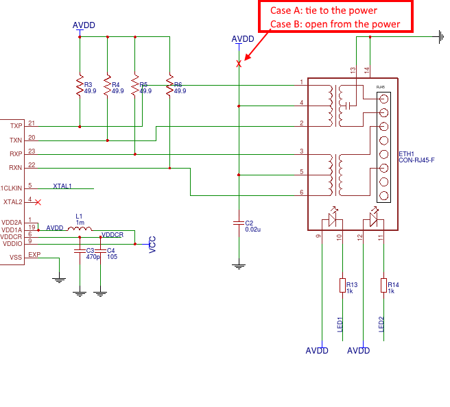
The following circuit diagram is for LAN8720a interface circuit.

It should be connected to the AVDD directly (Case A in the image).
But some other PHY application circuits are different (Case B).

Ethernet Interface Circuit

Now, I have some questions:

  1. Why application circuits are different according to the PHY?

  2. What is happenning if I connect the center tap to the power for the Case B PHY?

Thank you.

\$\endgroup\$
1
  • \$\begingroup\$ There is no generic PHY. \$\endgroup\$
    – Andy aka
    Commented Feb 1, 2018 at 11:28

1 Answer 1

6
\$\begingroup\$

It depends on the output type of the PHY.

If it has open-drain outputs then it requires the center tap to be connected to Vcc. If it has push-pull outputs then the center tap has to float.

There are probably silicon-level trade-offs like area vs. power vs. speed vs. EMC vs. manufacturing process etc. that lead to choosing open-drain or push-pull configuration.

If you connect the center tap to Vcc for a PHY that does not allow that then in the best case it may just work, or it may only work for a particular speed, or it may not work, or you will blow the chip.

\$\endgroup\$
0

Your Answer

By clicking “Post Your Answer”, you agree to our terms of service and acknowledge you have read our privacy policy.

Not the answer you're looking for? Browse other questions tagged or ask your own question.