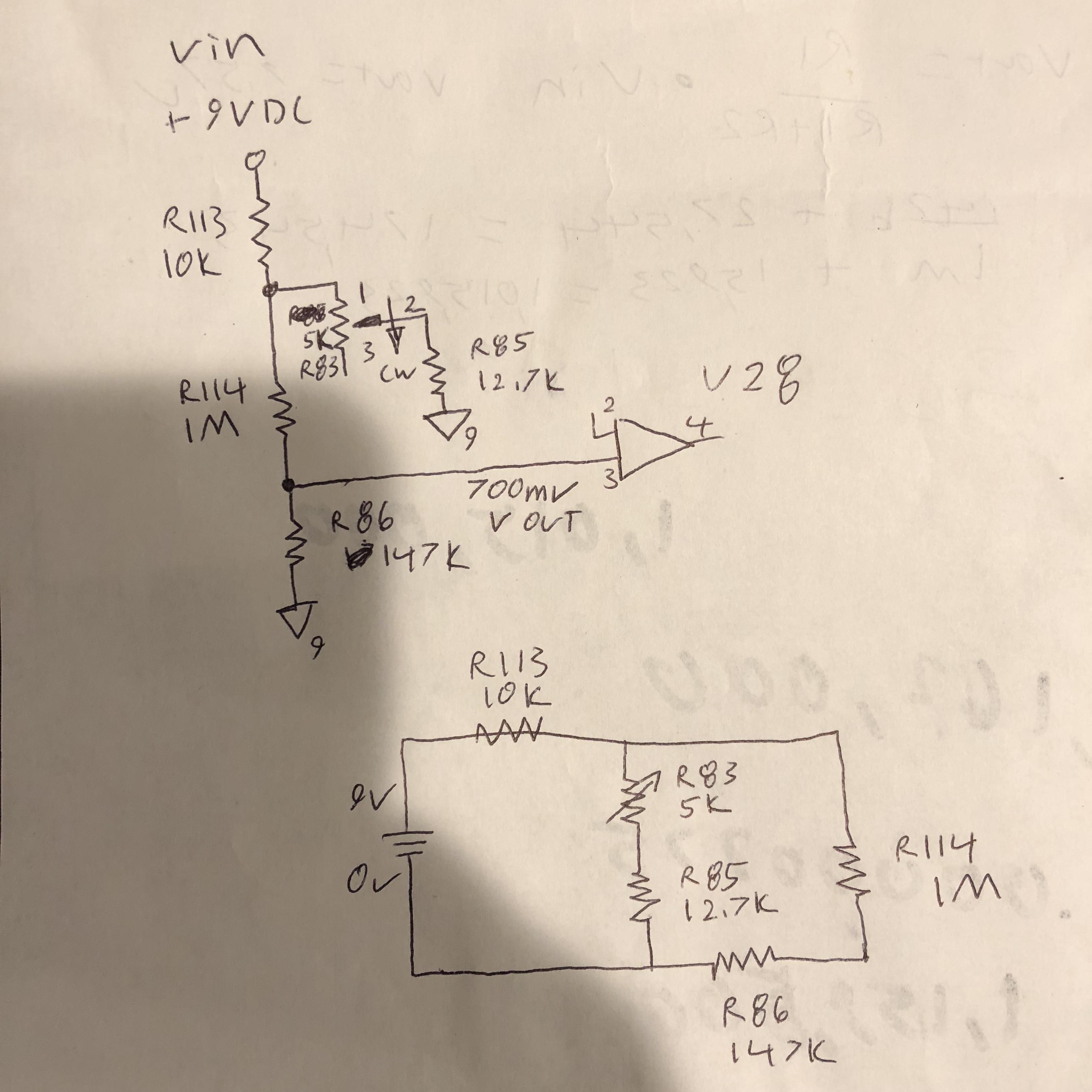
Hello I am troubleshooting a voltage divider circuit in which I know the output going to U28 pin 3 should be around 700mv. What I am measuring however is around 7.5v. How do I calculate the v out for this circuit. I know I have to account for R83 because it is a potentiometer but still I should be able to math this out and get close to 700mv but I can’t seem to calculate it right even after watching YouTube. The top photo is the actual schematic drawing but I redrew it to in the way in which I thought it works because I noticed r85 and r86 share the same ground therefore r83 and r85 must be in parallel to r114. So did I draw this out right and how do I solve for vout?
-
\$\begingroup\$ R114 and R86 are also in parallel. \$\endgroup\$– CNACommented Mar 24, 2018 at 4:53
-
\$\begingroup\$ Welcome to EE.SE. Remember that resistor voltage dividers can be treated as simple ratios. If Vin is R1 and R2 is ground, then the voltage between them is equal to the ratio of R1/R2. For simple stuff treat them as just plain integers. \$\endgroup\$– user105652Commented Mar 24, 2018 at 5:07
-
\$\begingroup\$ If I assume that your "ground" node on one end of \$R_{85}\$ in the first diagram is actually connected to the node shared by pin 3, then I'd get something near \$7.5\:\text{V}\$ on pin 3. Could you double-check that wiring? \$\endgroup\$– jonkCommented Mar 24, 2018 at 5:35
-
\$\begingroup\$ Hi jonk you are talking about pin 3 next to r83 right not u28? R83 is a thermometer adjust. The why I drew the schematic is exactly how it is. I’m not sure if I am understanding what you are saying but do you mean that pin 3 of the thermometer is ground. \$\endgroup\$– PilotCommented Mar 24, 2018 at 6:13
-
\$\begingroup\$ @Pilot I'm not thinking that, at all. Here's the thing. You are measuring about \$7.5\:\text{V}\$ on pin 3. I'm taking that as gospel from you. So that means I am NOT suggesting it is connected to ground, because I believe you made a correct voltage measurement at pin 3. I really do. \$\endgroup\$– jonkCommented Mar 24, 2018 at 6:31
2 Answers
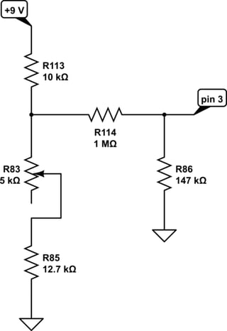
The circuit can be redrawn (always a good idea) like this:

simulate this circuit – Schematic created using CircuitLab
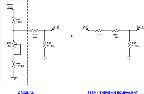
There are a couple of approaches to solving the voltage value for pin 3. The one that is likely taught earlier would use a process of applying Thevenin equivalents. Let's do that:

Here, \$V_\text{TH}=9\:\text{V}\frac{R_{83}+R_{85}}{R_{83}+R_{85}+R_{113}}\$ and \$R_\text{TH}=\frac{R_{113}\cdot\left(R_{83}+R_{85}\right)}{R_{83}+R_{85}+R_{113}}\$.
At this point, it's a simple voltage divider. Let's pause for a moment and look at it more closely before moving on to the next step. Here, you can see that \$R_\text{TH}\$ is followed by a \$1\:\text{M}\Omega\$ resistor. Since \$R_\text{TH}\$ can't be very large by comparison (a few thousands of Ohms, but nothing close to the value of \$R_{114}\$), we can easily see even at this point that the potentiometer can only vary the pin 3 voltage a little bit. I think that's clear at this point, already.
The above was step 1. But there is another step yet needed to get the pin voltage:
$$\begin{align*} V_\text{pin 3} &= V_\text{TH}\frac{R_{86}}{R_\text{TH}+R_{114}+R_{86}}\tag{Step 2}\\\\ &=9\:\text{V}\cdot\frac{R_{83}+R_{85}}{R_{83}+R_{85}+R_{113}}\cdot\frac{R_{86}}{\frac{R_{113}\cdot\left(R_{83}+R_{85}\right)}{R_{83}+R_{85}+R_{113}}+R_{114}+R_{86}}\\\\ &=9\:\text{V}\cdot R_{86}\cdot\frac{R_{83}+R_{85}}{R_{113}\cdot\left(R_{83}+R_{85}\right)+\left(R_{114}+R_{86}\right)\cdot\left(R_{83}+R_{85}+R_{113}\right)}\\\\ &=9\:\text{V}\cdot \frac{R_{86}}{R_{113}+\left(R_{114}+R_{86}\right)\cdot\left(1+\frac{R_{113}}{R_{83}+R_{85}}\right)}\tag{Final} \end{align*}$$
That last step is actually very helpful because it isolates potentiometer \$R_{83}\$ and allows you to see better what impact it has on the whole structure of the answer here.
Another approach would be to use nodal analysis and solve the simultaneous equations (two of them.) But the result would be the same and the above relies on limited knowledge of less powerful tools (if perhaps still some algebra.)
I would still like to hear about what you find in your process of tracking down the problem, too. Please let us know what you find.
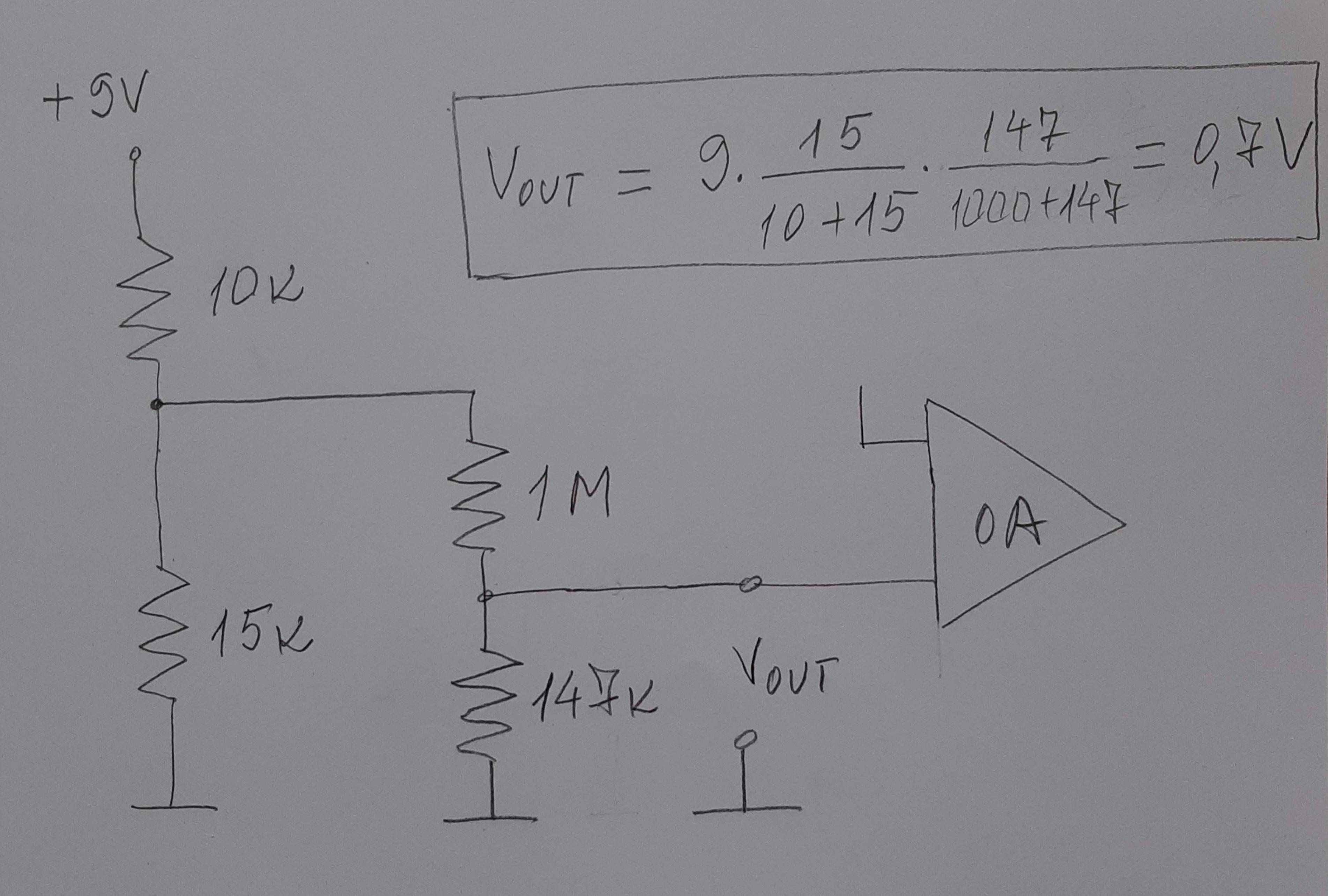
This mixture of resistors can be presented as two cascaded voltage dividers since the second one has high input resistance and loads slightly the first. The variable resistor should be considered in the middle position (R = 2.5 k). Then VOUT = 9.15/(10 +15) x 147/(1000 + 147) = 0.7 V.

