1
\$\begingroup\$

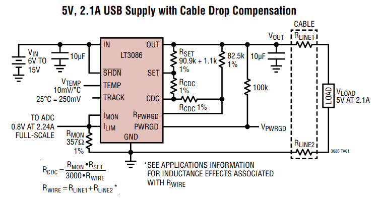
In my project I am using a LT3086 (40V, 2.1A Low Dropout Adjustable Linear Regulator with Monitoring and Cable Drop Compensation )

LT3086

With this voltage regulator you can "programm" the output current limit by connecting the pins Imon and Ilim and by setting the resistor Rmon to a correct value. (as shown in the picture above)

The relation between resistance Rmon and output current limit Ilim value is given by this equation (datasheet page 13):

Ilim = 800/Rmon

My goal would be to control the current limit between 5mA and 1A, where:

  • Ilim = 1A at Rmon = 800 ohm
  • Ilim = 5mA at Rmon = 160 kohm

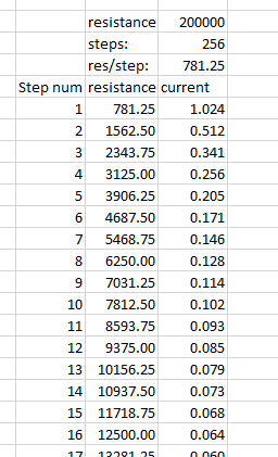
My initial plan was to implement one digital potentiometer with a value 200K and with 256 steps (781.25 ohm/step). Since the equation for setting the current limit Ilim is not a linear function, you can not get a good resolution for the higher current values, but as you get higher in resistance the resolution gets better.

non linearity

To counteract that, my plan is to implement a series of digital potentiometers (256 step) to simulate a digital logharithmic pot (I couldnt find any log pot that would sufice).

schematic

simulate this circuit – Schematic created using CircuitLab

enter image description here

And this would all work fine in ideal conditions...but the world is not ideal. 800 ohm resistor would be used if there was no wiper resistance and no 1. step resistance (when there is address 0). Wiper resistance can be between 75 and 300 ohms.

So by using 5 digital pots in series at address 0 and with the wiper resistances, in the best scenario, I would get around 1023 ohms.

R=75+3.9+75+19.5+75+39+75+195+75+390=1023.4375

By putting it in the equation, the maximum current limit and with that current at all, I could control with that would be:

Ilim = 800/1023 = 0.782 A

Which is far from 1 A.

Finally, the question:

How would I precisely compensate for the wiper+1.step resistance to get the resistance of 800 ohms, so I could set the current limit upto 1A?

\$\endgroup\$
2
  • \$\begingroup\$ I see a number of problems here. The wiper resistance is too high and variable from part to part. The tolerance of the digital pots is typically +/- 20% so that is going to introduce a large error that will need to be calibrated for. I am thinking another approach would be to replace the digital pot with a DAC that sinks current to ground. You could use something like a 16 bit DAC that would give the resolution you are looking for. \$\endgroup\$
    – EE_socal
    Commented Apr 11, 2018 at 19:58
  • \$\begingroup\$ Another thought I had is to put the digital pots in parallel instead of series. Connect each one to ground using a N-Channel MOSFET to switch them on and off. So if the 1K pot selected you are going have a resistance between 75 and 300 ohms for the wiper plus 3.9 ohms at the lowest setting. You still are going to need to have a lot of calibration for each unit. \$\endgroup\$
    – EE_socal
    Commented Apr 11, 2018 at 20:28

2 Answers 2

1
\$\begingroup\$

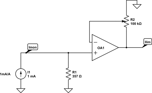
The limiting current is established when the Ilim input exceeds 800mV, so you can simply make an amplifier to amplify the voltage.

schematic

simulate this circuit – Schematic created using CircuitLab

It should limit at Iout = \$\frac{0.8V\cdot\sigma}{R_S\cdot 0.001}\$ where \$0\le\sigma\le 1\$ is the digital pot "rotation"

\$\endgroup\$
0
\$\begingroup\$

This is just a suggestion to get you going.

schematic

simulate this circuit – Schematic created using CircuitLab

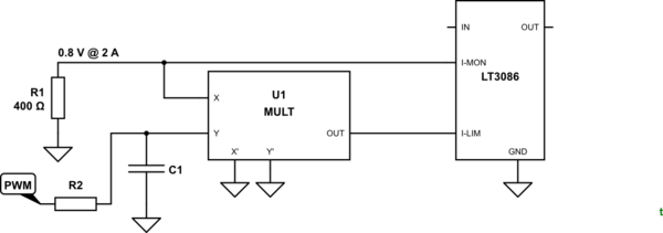
Figure 1. Using an analog multiplier to set the gain of the I-mon signal for digitally controlled current limit.

How the scheme works:

  • Analog multipliers such as the ancient AD633 (I think) have an output given equal to \$ OUT = \frac {X \cdot Y}{10} \$. Ideally you would find one that will work down to 0 V on a single supply and have an adjustable K value (see below). You only require single-quadrant mulitplication as both values will be positive.
  • Set R1 to give 0.8 V at the maximum current you want to measure. Note that the max value listed in the datasheet is 1k so your 160k idea may not work.
  • At 5 mA output current you will have 5 µA x 400 Ω = 2 mV across R1. The U1 multiplier will require a gain of 400 to raise this to 800 mV to activate the I-LIM.
  • Assuming the PWM can give you Vy = 0 to 5 V then for 5 mA you will require

    • Vx = 2 mV
    • Vy = 5 V
    • Vout = 800 mV
    • Multipication factor = \$ \frac {800m}{2m \cdot 500m} = 800 \$.

I don't have the energy to develop this any further for you.

\$\endgroup\$

Your Answer

By clicking “Post Your Answer”, you agree to our terms of service and acknowledge you have read our privacy policy.

Not the answer you're looking for? Browse other questions tagged or ask your own question.