0
\$\begingroup\$

Design Criteria

For a project I'm making I want to measure temperature using a 10 bit ADC on a MCU.

I don't care for absolute accuracy but I would like precision down to around 1/10th of a degree C.

To clarify I'm fine with a bias and gain error and even weak non-linearity , as long as the random error (noise) is low and measurements are consistent between readings of the same temperature.

The sensor will be powered and read once per hour so self heat-up shouldn't be an issue.

I expect that the temperatures I will measure are around 10-40 C. However to have some design headroom I chose to use the range [-40,+100] C as my design criteria when sizing the passives.

Chosen RTD

I chose to do this with a RTD. The particular one I'm looking at has:

  • 0C = 100 R
  • -50C = ~70 R
  • +100C = ~140 R

Circuit

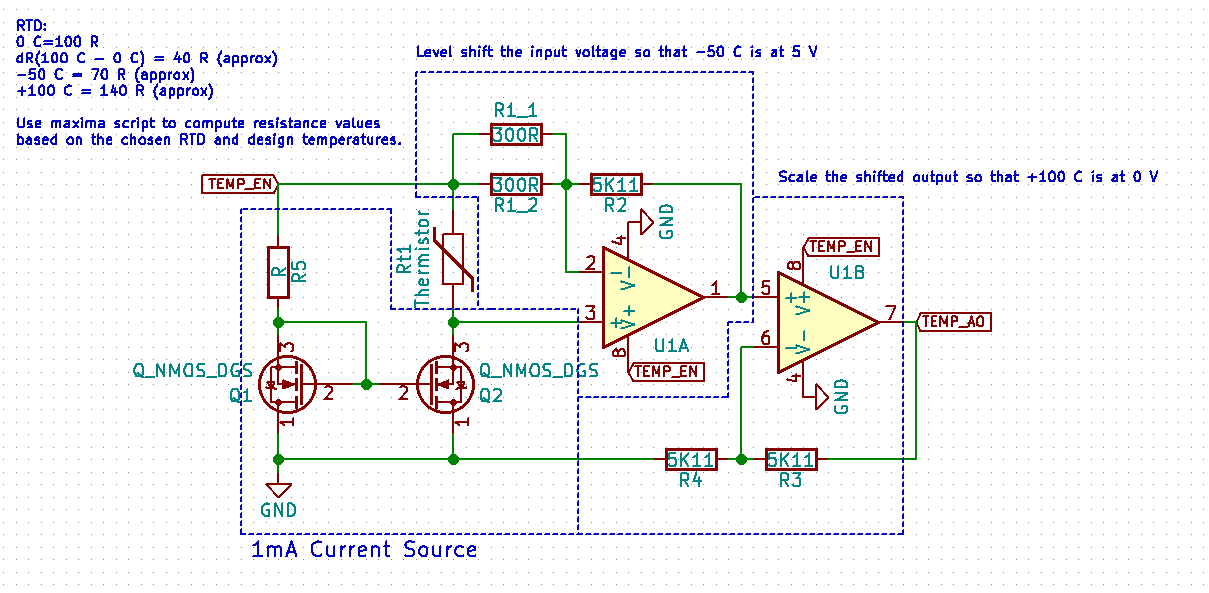
The circuit I have come up with is shown below. It has four major components:

  • A 1mA current source to bias the RTD.
  • A level shift of the RTD sense.
  • A scaling of the RTD sense.

The goal of the level shift and scaling of the sensed RTD value is to scale the range of [-50C, +100C] to [5V, 0V] to get maximal use of the 10 bit ADC on the MCU.

The TEMP_EN is connected to a GPIO pin on the MCU, driven high prior to measuring the output with the ADC. The GPIO pin can drive 20 mA max.

I have chosen 300R and 5K11 resistors for this design as they are used elsewhere in the project and actually form very close to the required ratios for the voltage dividers by a happy coincidence.

A simulation of the circuit can be found here.

Circuit Diagram

I used WxMaxima to calculate the resistor values: Calculations
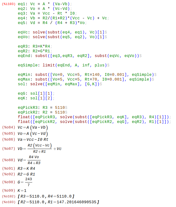
Where:

  • Va = sensed voltage after RTD
  • Vb = negative input to first op-amp
  • Vc = positive input to second op-amp
  • Vd = negative input to second op-amp
  • A = op-amp gain (assumed ideal later)

I expect 150 C / 2^10 = 0.15 C precision on the measured value.

Question

This is my first time working with Op-Amps after my EE course in Uni which was a long time ago. And my first time building a constant current source. I would very much like input on the design of the current source, will it be good enough? Are there easy modifications I can make to make it better for this application?

Can I expect the circuit to have reasonable noise resistance? The environment is a typical home environment and TEMP_AO is connected via a 30-50cm shielded, otherwise quiet cable to the MCU.

Should I decouple the op-amps? There isn't any switching going on here so I'm unsure if they are needed.

I have the shift before the gain. Should I change the order to do gain first and then shift? Which is better?

Any other considerations I should make?

\$\endgroup\$
3
  • 1
    \$\begingroup\$ NTC thermistors have very high accuracy, far higher gain, and are easier to use at these temperatures. Unless you have a good reason to use Pt-RTD, they are a better choice. \$\endgroup\$
    – Henry Crun
    Commented May 21, 2018 at 9:39
  • \$\begingroup\$ @HenryCrun that is a very nice observation, thank you. I think an NTC might be better for to me. It looks like I then don't need the current source. I can just use a voltage divider to reduce the nonlinearity enough and op-amp it up and send to ADC. \$\endgroup\$
    – Emily L.
    Commented May 21, 2018 at 13:33
  • \$\begingroup\$ Yes---provide Local charge sources for the opamps. Use 10uF right at the opamp VDD pin. And place 10 ohm resistors between that VDD pin and the central bulk/raw supply. Or even 100 ohm. 10uF * 100ohm is 1milliSec tau, or 160Hz F3dB, thus the fast-edge high dI/dT of power supply diodes will be attenuated, and the Opamps' PSRR will have less performance requirements. \$\endgroup\$ Commented Sep 20, 2018 at 16:30

4 Answers 4

2
\$\begingroup\$

DIN standard 100 ohm RTDs are 100 ohms at 0'C and 138.50 ohms at 100'C.

Starting at the beginning, your switched current sink looks quite inadequate. You need it steady to within +/-0.03% for 0.1'C, and it depends on the (noisy) GPIO voltage of a micro vs. the (poorly defined and temperature-sensitive) Vgs of the MOSFET Q1 (and the matching to Q2, and some other stuff). Wrap an op-amp around the current sink for sure, and give it a proper reference voltage, not the supply voltage of the micro.

Even if you have a so-called rail-to-rail op-amp you should not work right to 0V and 5V if you actually are required to read those corresponding temperatures. Knock a bit (depending on the op-amp) off each end and live with reduced resolution.

As far as EMI susceptibility goes, you should put some low pass filtering ahead of the amplifier. 0.1'C is about 38.5uV DC which is a rather healthy signal at DC, but it's easy for noise, hum etc. to creep in.

Whether self-heating is an issue or not depends on the time constant of the RTD in the measured medium (including whatever protection tube or other materials are present) vs. your measuring time (probably you want to average a number of readings).

I would suggest not switching the current to the RTD unless you have some reason to do so. It will just cause a small offset that is relatively stable.

\$\endgroup\$
7
  • \$\begingroup\$ Could you elaborate on wrapping the current sink in an opamp, I don't quite understand what you mean? The edges of the operating region of the opamp if far outside of the expected voltage output range. Should I filter ahead of both op amps? Or just the first? And thank you for your feedback. \$\endgroup\$
    – Emily L.
    Commented May 20, 2018 at 23:34
  • \$\begingroup\$ Have a look at this Microchip app note for a relatively simple approach (you may have to change some values for your situation). I'm not a big fan of their filtering (seems like a student approach, it would never pass industrial conditions) but if you slap some caps (eg. 10n) across the input terminals to ground it's probably okay for your relatively benign situation. \$\endgroup\$ Commented May 20, 2018 at 23:40
  • \$\begingroup\$ By wrapping an op-amp, I mean drive the gate of a single MOSFET with an op-amp, use a sense resistor in the source and feed it a suitable reference (eg. 0.25VDC, perhaps divided down from an accurate/stable 2.50V reference). If you look up current source/sink you will find this is a standard building block. \$\endgroup\$ Commented May 20, 2018 at 23:44
  • \$\begingroup\$ Oh cool thing with the op-amps to create a current source and removing the wire resistance using a subtracting opamp (whatever you call that arrangement). Based on Henry's comment I've decided to o with a NTC thermistor instead, I think it'll suit my application better. I'll accept your answer nonetheless. \$\endgroup\$
    – Emily L.
    Commented May 21, 2018 at 16:23
  • 1
    \$\begingroup\$ CHALLENGE ACCEPTED :P \$\endgroup\$
    – Emily L.
    Commented May 21, 2018 at 18:20
1
\$\begingroup\$

You will find it easier to use a PT1000 1k resistor - less current, higher voltage for the same heating.

I can't see your current mirror arrangement being vaguely workable - you need current to be accurate to 1/5000.

Filtering (i.e. a capacitor across R3) would reduce noise, though it will not the opamp noise that is the issue. You should always have decoupling capacitors, and you should have some RF filtering capacitors in the input circuit.

As a matter of interest, there are lots of good and proper ways to do it, and then there is this way....

My son was able to use PT1000 with a simple voltage divider with a picaxe micro, by summing 10bit ADC readings 16x. (ie. averaging)

0.1C is about 1/2500 resolution of resistance, so it may work.

Of course this requires a noisy enough ADC to fuzz the input by ~1 bit.

You plot a histogram of the residual after dividing but the N sum, you can see if the averaging is working - do you have enough noise.

\$\endgroup\$
1
\$\begingroup\$

Do decouple opamps, 1uF across the supply.

Temperature is easier to measure with just pull up. Ok, you may want to use 3 or 4-wire scheme to compensate the wires, but definitely you don't need a current mirror. For PT100 and 1mA current you would get a very linear behavior. But if this is not linear enough- take ten points look up table and interpolate.

A good filter will give you your 10 bits. Be sure to use a very low drift opamp, so circuit temperature will not hurt.

Maybe the best you can do is to run few simulations. Not for noise of course, but to see that gain and offset are all good. Use ltspice. Check how resistors of 1% behave vs 0.1%

\$\endgroup\$
5
  • \$\begingroup\$ I'm sorry but your explanation makes no sense to me. Using a pull up to measure is a foreign concept as it's just a resistance to Vcc. It doesn't measure anything... What do you mean by filter? Analog domain? Digital domain? I did the simulations for my circuits and circuit analysis to determine the gains and offsets. \$\endgroup\$
    – Emily L.
    Commented May 21, 2018 at 16:20
  • \$\begingroup\$ Makes no sense because little experience, sorry. So pull up meaning it's enough to do like that: 5V -\/\/\- PT100 GND. The redistor- 5k, so the current will be around 1mA. Voltage on PT100 is amplified by analog amplifier (very simple) with some gain (probably 30 to 50) and bandwidth (probably 100Hz to 1kHz). That's it. Very simple, otherwise it's for advanced engineers. In your MCU you can do running average, that's the most "complex" digital filter you may need for this application. Is it more clear now? \$\endgroup\$
    – user76844
    Commented May 21, 2018 at 16:27
  • \$\begingroup\$ Ok so what you're describing is a voltage divider and you want to take the voltage at the midpoint. This is not a pull-up. A pull up is used to drive a line high when there is no one actively driving it low. Using a voltage divider like that was my first idea and I discarded it early in the process. Then I did the amplification/shifting as in the question. And maybe it would work with that circuit. \$\endgroup\$
    – Emily L.
    Commented May 21, 2018 at 17:02
  • \$\begingroup\$ Glad you understand. Did you understand that you don't need current source? Did you understand why? Do you understand why simplicity matters? \$\endgroup\$
    – user76844
    Commented May 21, 2018 at 17:09
  • \$\begingroup\$ By the way. If you are worried about the wire resistance (i don't think you should be, but still), go for 4-wire scheme, which is in fact much like 4-point resistance measurement. \$\endgroup\$
    – user76844
    Commented May 21, 2018 at 17:12
0
\$\begingroup\$

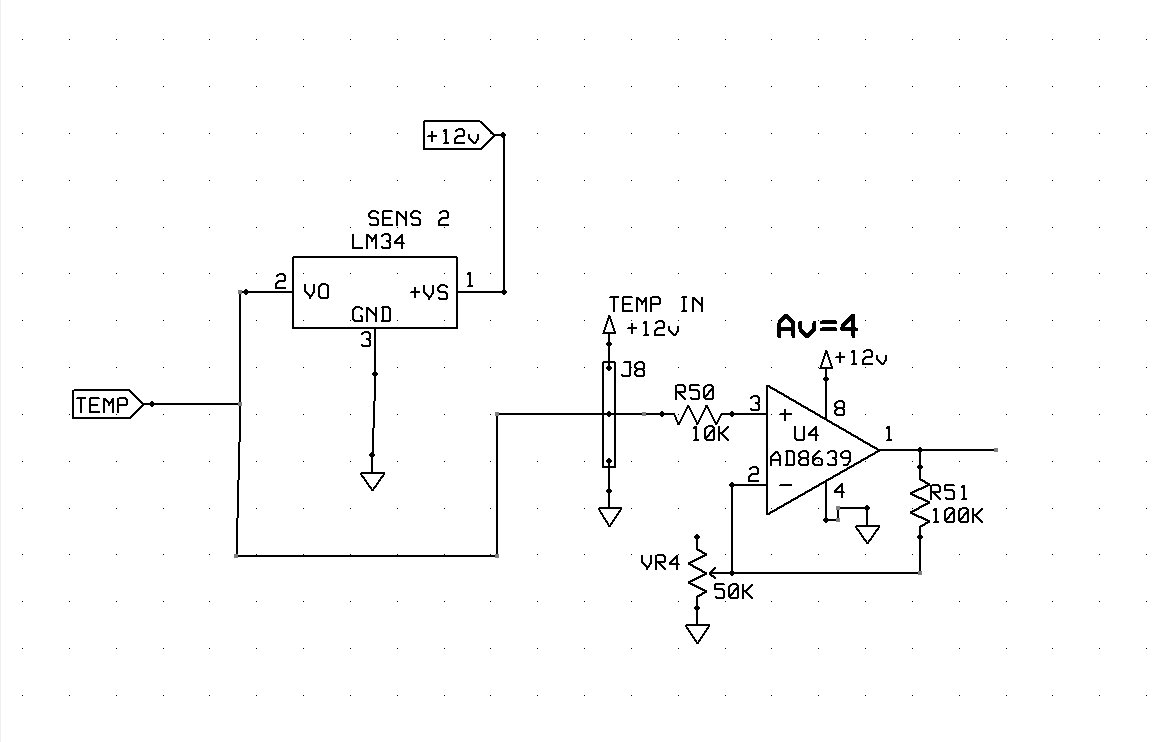
Here is a tested VASTLY simplified temperature sensor circuit I have used. The Amplifier is a chopper stabilized zero offset error amp, And the sensor is 10 mV/degree completely linear output. Some very simple math will give you the necessary output to the Micro. If you are attempting to get 10 bit stability, you can't beat this.enter image description here (Please guys, I am well aware there are SOME tolerances) But non the less, this is far superior in linearity and stability as you are going to find for the price. The op-amp and sensor can be purchased off Digikey, and I believe the AD8639 can be bought as a single circuit 8 pin dip.

\$\endgroup\$
2

Your Answer

By clicking “Post Your Answer”, you agree to our terms of service and acknowledge you have read our privacy policy.

Not the answer you're looking for? Browse other questions tagged or ask your own question.