1
\$\begingroup\$

enter image description here

Hello,

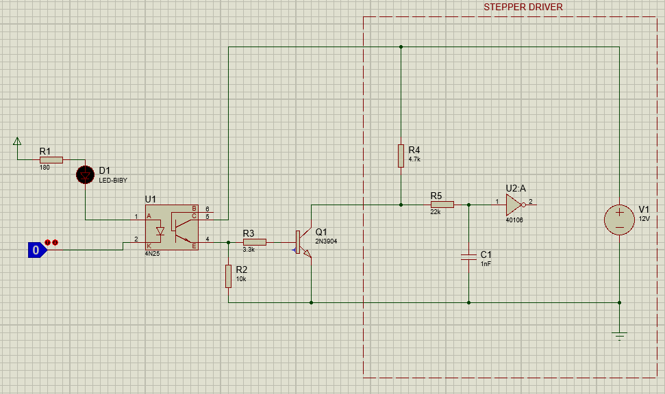
I have designed this optocoupler interface to an stepper driver. However, I'm not sure if it's all right. For R1 I made (5-3.3)/10mA ≈ 180 ohms. 3.3V taking into account the two leds voltage drops.

The output part is the one confusing for me. It's an open collector configuration that will be connected to the stepper as shown. I know that the circuit could be done without the 2n3904, but I want to include it. What do you think about the values of R2=10k and R3=3.3k? I'm not experted at designing so I'm asking for your suggestions. I'm not taking the CTR concept into account. Also I need to review the currents to be sure that it's all right at the output.

The circuit part inside the box is an input of the driver, so it's unmodifiable.

\$\endgroup\$
5
  • \$\begingroup\$ " I know that the circuit could be done without the 2n3904, but I want to include it." - Why? \$\endgroup\$ Commented Apr 25, 2018 at 20:02
  • \$\begingroup\$ To be honest, someone is asking me to build that, and I tried to convice him that the 2n3904 might not be needed. But he told me about using that in other stepper drivers that could have different electrical characteristic so he wants versatility. Still confused, so I had no more choice than to include the 2n3904. \$\endgroup\$
    – user115094
    Commented Apr 25, 2018 at 20:12
  • \$\begingroup\$ At what frequency are you switching? \$\endgroup\$
    – CL.
    Commented Apr 25, 2018 at 20:23
  • \$\begingroup\$ Don't have the specific value, but according to the stepper driver datasheet, the step and direction signals can't be higher than 50kHz. \$\endgroup\$
    – user115094
    Commented Apr 25, 2018 at 20:26
  • \$\begingroup\$ If the actual signals are faster than about 5 kHz, using an H11L1 is easier than using additional components to speed up and amplify the 4N25's output signal. \$\endgroup\$
    – CL.
    Commented Apr 26, 2018 at 17:08

1 Answer 1

0
\$\begingroup\$

The stepper driver input is pulled up internally by R4. At 12 V and 4.7 kΩ, it takes only 2.6 mA to pull the input solidly low. That's well within the range of common opto-couplers. You can simply connect the opto output between the stepper driver input and ground. R2, R3, and Q1 are just silly.

Other than that, work backwards to make sure you are driving the LED in the opto with sufficient current. That needs to be at least 2.6 mA divided by the current transfer ratio. It's good to leave some margin, so you probably want to have the nominal current be maybe 50% higher than the minimum necessary value.

No, you don't get to just ignore the current transfer ratio.

\$\endgroup\$
3
  • \$\begingroup\$ A saturated phototransistor will not switch at 50 kHz. \$\endgroup\$
    – CL.
    Commented Apr 26, 2018 at 17:00
  • \$\begingroup\$ @CL. 1: Not true. 50 kHz is 20 us period. There are plenty of optos that can switch on and off in well under 10 us. 2: Stepper motors don't run at 50 kHz. 3: It is irrelevant anyway. I just re-read the whole question, and the OP has said nothing about 50 kHz. It is not a requirement. 4: A separate NPN with a 10 kOhm pulldown on its base, as the OP is proposing, isn't going to switch very fast either. \$\endgroup\$ Commented Apr 26, 2018 at 17:33
  • \$\begingroup\$ @OlinLathrop I understand perfectly what you said about R2, R3 and Q1. But let's imagine that we are going to include them. The 10 kOnm resistor, are you suggesting to remove it? \$\endgroup\$
    – user115094
    Commented Apr 27, 2018 at 17:37

Your Answer

By clicking “Post Your Answer”, you agree to our terms of service and acknowledge you have read our privacy policy.