2
\$\begingroup\$

Situation

I'm looking to add Raspberry Pi 3 near my door and detect when the doorbell is pressed. But I don't want it to change the operation of the chime (if Pi is off/unplugged, the chime should still work). I don't want to put something next to the chime because all of my connections/electronics are near the doorbell button itself.

I saw this question and that diode rectifier looked interesting.

This is the circuit I'm thinking of Circuit I read that the Opto-Isolator wears out 50% in 5 years, so in series it would only be on when pressed, as opposed to reverse logic and using the NC side of the button.

Can I put that rectifier in series with my chime?

R1,R2 are power resistors

\$\endgroup\$
4
  • \$\begingroup\$ You will need to drop around 3V for this circuit to work reliably. Can your doorbell work reliably with ~9V rather than 12V? \$\endgroup\$ Commented May 1, 2018 at 19:12
  • \$\begingroup\$ Most doorbell transformers can be set to a variety of voltages. Check whether it can be set a bit higher. \$\endgroup\$
    – Janka
    Commented May 1, 2018 at 19:15
  • \$\begingroup\$ @Janka This transformer has just one set of output terminals. \$\endgroup\$ Commented May 1, 2018 at 22:56
  • \$\begingroup\$ @SpehroPefhany I don't know, I will see if I have another transformer to test with. I would suspect not or at least not as loudly? \$\endgroup\$ Commented May 1, 2018 at 22:58

2 Answers 2

1
\$\begingroup\$

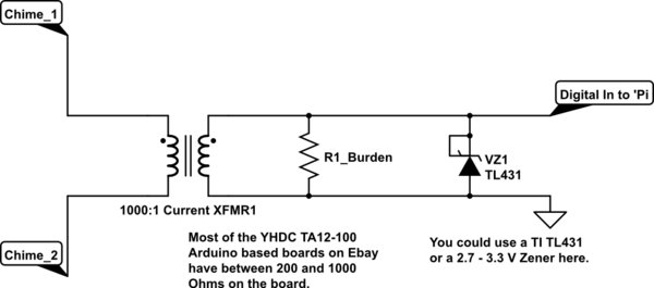
Providing that your Chime power supply feeding the pushbutton(s) is 12 VAC, I'd suggest a somewhat simpler schematic:

schematic

simulate this circuit – Schematic created using CircuitLab

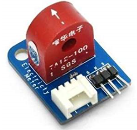
These current transformers are readily available as an Arduino type sensor for measuring 5A AC full scale. They are ideally suited for sensing presence or absence of AC current and won't interfere with your Chime circuit at all.

It's likely that your Chime is using something between 2-5W when activated, so you expect current flow at 200mA or above when activated. You can pass the pushbutton wire through the current transformer up to say 5 times which would give about 1A full scale from the current transformer. At this full scale setting with only the burden resistor on the sensor board, you should get a nice pulse going into the 'Pi digital pin.

Search for Arduino AC current sensor on Ebay or Amazon, you should find lots like this:

enter image description here

\$\endgroup\$
0
\$\begingroup\$

So it turns out that I happened upon a switch that is perfect for this situation!

https://www.adafruit.com/product/3423

The product description says that

There are two electrically separate SPST switches inside the button.

and

The switch and LED are electrically separated,

\$\endgroup\$

Your Answer

By clicking “Post Your Answer”, you agree to our terms of service and acknowledge you have read our privacy policy.

Not the answer you're looking for? Browse other questions tagged or ask your own question.