1
\$\begingroup\$

I have a RCWL-0516 doppler radar microwave motion sensor module which I want to start using a on/off wireless controller.

When the wireless controller is on, it outputs a 3V continuous signal, while when it is off, it does not output any signal.

Since the RCWL-0516 needs at least 4V to operate, I can not use the 3V output from the wireless controller to start it so I thought of using a N2222A npn transistor as a switch.

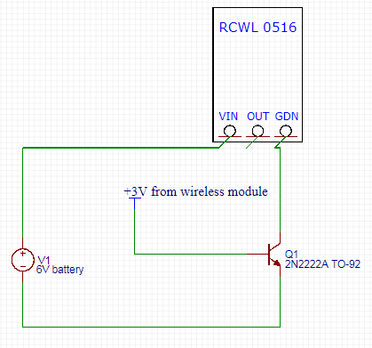
For this, I have connected the emitter to ground, the 3V signal from the wireless controller to base and the ground pin from RCWL-0516 to collector while the VIN pin from RCWL-0516 I have connected to +6V.

With this configuration, when the wireless controller sends 3V, the RCWL-0516 is working as it should however when the wireless controller does not send 3V (is off) then the RCWL-0516 module is sending constant high signal to the OUT output.

So it seems that if RCWL-0516 is not connected to ground and is only connected to the +6V from VIN, it will output high to the OUT pin.

So this configuration is not suitable for my project.

Is there a way where I can control only the +6V which is being sent to RCWL-0516 while it is always connected to the ground ? I have tried to connect the VIN of RCWL-0516 to emitter while the GDN pin to ground however it did not work.

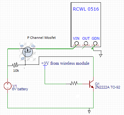
I have also tried to use a IRF520 mosfet driver but it seems that the 3V from the wireless module is not able to start the mosfet. enter image description here
\$\endgroup\$
3
  • \$\begingroup\$ Put a limiting resistor between 3V and the base. \$\endgroup\$ Commented May 9, 2018 at 7:57
  • \$\begingroup\$ I have tried this but it did not help. When there is current from the 3V wireless module and the transistor is ON, the RCWL-0516 works good, as both the VIN and GDN pin are connected. But when there is 0V from wireless module and the transistor is off, the VIN of RCWL-0516 gets the 6V from battery while the GDN is not connected (since transistor if OFF), so in this case, the RCWL-0516 is always outputing high on the OUT terminal \$\endgroup\$ Commented May 9, 2018 at 8:01
  • \$\begingroup\$ I think the best way would be to have the GDN of RCWL-0516 pin always connected to negative terminal of battery while the transistor to turn ON/OFF only the +6V from battery that goes to VIN of RCWL-0516. Is this possible to do? \$\endgroup\$ Commented May 9, 2018 at 8:03

1 Answer 1

1
\$\begingroup\$

What's happening is that power is flowing into VIN, and it has nowhere to go, so GND is floating up until it's equal to VIN.

The sensor OUT will never lower than GND due to protection diodes so you end up seeing VIN at the output.

I would recommend using a high side switch to solve this problem. Like this: enter image description here

\$\endgroup\$
1
  • \$\begingroup\$ Thank you! I have tried this implementation and it worked. \$\endgroup\$ Commented May 10, 2018 at 11:20

Your Answer

By clicking “Post Your Answer”, you agree to our terms of service and acknowledge you have read our privacy policy.

Not the answer you're looking for? Browse other questions tagged or ask your own question.