3
\$\begingroup\$

I want to use a pair of N and P channel mosfets in a totem pole arragement to shift a VFD display on and off using a 74LS247 decoder/driver. I would put the P channel with the source pin on the top and connected to the 25 volts the VFD requires. The P channel drain pin would be connected N channel drain pin. The junction of both drains would be my output (25 Volts). The source pin of the N channel would be connected to ground.

The gates of both the P and N channel mosfets would be tied together and powered from the "Open Collector" output of the 74LS247 decoder/driver to turn on and off the appropriate mosfet. I plan on using a Fairchild FDS8958A mosfet complementary pair.

Questions:

  • Do I need a series resistor in series with the LS247 output and the two gates?

  • What value do I need?

  • Do I need pullup / pulldown resistors between the source pin and gate pins?

\$\endgroup\$
2
  • \$\begingroup\$ What they said ... but ... do you need the low side driver as opposed to some sort of load to pull the P Channel drain low when it is off. If you need any sort of speed or power in the pull down then an active pair makes sense but if slow and just on or not on then a single FET and pull down may make sense. | Always watch out for Vgsmax in situations like this. In this case they do not seem to say (they give Vgs of 10V but that's presumably not max). \$\endgroup\$
    – Russell McMahon
    Commented Jan 17, 2015 at 2:05
  • \$\begingroup\$ @RusselMcMahon Vgs max of +/-20V (for both MOSFETs) is about halfway down the first page of the datasheet, in the "absolute maximum ratings" section. \$\endgroup\$
    – markt
    Commented Jan 17, 2015 at 6:42

2 Answers 2

3
\$\begingroup\$

Sorry, but this isn't going to work, or at least not directly. Yes, you need a pullup, but if you use one you'll destroy the 247. Reason? The 247 outputs have a max voltage rating of 15 volts, and you need to drive to 25. If you do manage to drive the P-type gate to 25 (to turn it off) you will violate the gate-source maximum voltage Vgss of 20 volts for the N-type. And if you drive the 247 output low you will exceed the gate-source voltage rating of the P-type.

\$\endgroup\$
3
\$\begingroup\$

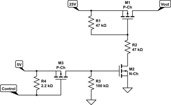
If you want to use a logic level to switch 25V, then I'd suggest an arrangement like this - a classic high-side switch.

The voltage divider on the gate of the P-Ch is to avoid Vgs exceeding the 20V limit for that part.

schematic

simulate this circuit – Schematic created using CircuitLab

The update that I've made to the circuit incorporates an extra P-channel MOSFET, M3, and a pullup resistor to 5V, R4. This can be pretty much any modest P-Ch MOSFET; it should be reasonably fast but it doesn't need to be high voltage or high current. Its purpose is to convert the open-collector output from your 74LS247 into a 5V logic level. Alternatively, you could use a pullup resistor (like R4) and an inverter, e.g. a single gate from a 74LS04.

If you could choose a different decoder IC than the 74LS247, one with a logic level output, then you could go back to the previous circuit.

Please do some testing with a single instance of the circuit to satisfy yourself that this does indeed work before you design and assemble a 42-channel version!

\$\endgroup\$
14
  • \$\begingroup\$ So the consensus is that the circuit which is shown will not work? It will destroy the 74LS247. So what do I need to do? \$\endgroup\$ Commented Jan 17, 2015 at 3:36
  • \$\begingroup\$ @EdEdmondson If all you want to do is switch the 25V on and off, then the above circuit will do it perfectly well - apply 1.9V or more to the Control input and you get 25V out. If you want to switch it at highish speed, e.g. with PWM, then the circuit will need some tweaking - change the 47K's to 1K's, perhaps. \$\endgroup\$
    – markt
    Commented Jan 17, 2015 at 3:46
  • \$\begingroup\$ Wouldn't a pair constituting a P and N channel mosfets in a totem pole with the gates tied together and tied to the output pin of the LS247 work? I was tying the source pin of the p channel to the 25 volts. I was then tying the source of the n channel to ground. Then finally tie the two drains together to provide the 25 volt / 0 volts output I would need. When the gates are high then the output would be low (Off). When the gates are high (the LS247 is on and the anodes are lit up) then I would have 25 volts on the output. Please forgive me if I have stepped on anyone's toes. \$\endgroup\$ Commented Jan 17, 2015 at 3:57
  • \$\begingroup\$ @EdEdmondson You're not stepping on anyone's toes, asking questions is the point of this site. WhatRoughBeast has explained why the totem pole won't work (and will kill your semiconductors). \$\endgroup\$
    – markt
    Commented Jan 17, 2015 at 6:41
  • \$\begingroup\$ Thanks for the clarification and enlightenment. I will use the above circuit to switch the Anodes (on & off) to my VFD using a 74LS247 outputs to each of the control inputs. The fastest speed would be about 2 Hz when in the time set mode. This is for a digital clock using Russian IV-11 VFD tubes. I will be assembling 42 (7 segments x 6 tubes) of these little control units on one PCB using 84 47K resistors and 42 100K resistors. \$\endgroup\$ Commented Jan 18, 2015 at 16:23

Your Answer

By clicking “Post Your Answer”, you agree to our terms of service and acknowledge you have read our privacy policy.

Not the answer you're looking for? Browse other questions tagged or ask your own question.