2
\$\begingroup\$

What symbol should I use to indicate a solid state relay in a schematic?

The internal schematic of the solid state relay is shown in the data sheet, but showing all of the internal components in the schematic is not necessary and would be more confusing than a single symbol.

\$\endgroup\$
2
  • \$\begingroup\$ Unless my schematics is too crowded I am using pretty much what's in datasheet. It makes it easier to understand the functionality. Otherwise I am just drawing generic box with named pins. Circuit Lab doesn't seem to have anything special for it. \$\endgroup\$
    – Maple
    Commented Jun 16, 2018 at 4:58
  • \$\begingroup\$ You can show it however you want to show it. It's just down to the opinion of the guy making the drawing. \$\endgroup\$
    – Andy aka
    Commented Jun 16, 2018 at 9:05

2 Answers 2

4
\$\begingroup\$

Use what is in the datasheet. Why? because it matters on what is inside the SSR. Is it optically isolated? Is it simply a mosfet, a triac or back to back mosfets?

With a single block it is impossible to tell. With a diagram inside the component you can tell what it's functionality is, saving some time. enter image description here
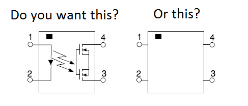
If you draw what is on the inside and put it in a library its easier for you to tell what it is and use it later on. This of course is all up to you, and it's every person for themselves on this one. If your using it in a group library, then consult your group.

\$\endgroup\$
1
\$\begingroup\$

schematic

simulate this circuit – Schematic created using CircuitLab

Figure 1. Home-made CircuitLab opto-isolators. (a) Standard transistor. (b) Opto-triac using the DIAC symbol as there is no gate terminal. (c) Bidirectional LED (a bit messy). (d) An opto triac or SSR with zero-cross.

I recommend showing the innards with enough detail to clearly identify

  • Function (the LED or switch).
  • Polarity (anode / cathode / collector / emitter / etc.).
  • Zero-cross if used.

This makes it very easy to confirm correct wiring and current flow (anode to cathode, for example). When the pin numbers are added to the symbol it makes conversion to physical layout much more easy.

\$\endgroup\$

Your Answer

By clicking “Post Your Answer”, you agree to our terms of service and acknowledge you have read our privacy policy.

Not the answer you're looking for? Browse other questions tagged or ask your own question.