0
\$\begingroup\$

I've spent the last hour trying to get an incremental encoder working with an mbed module.

Keyes KY-040 Rotary Encoder
https://www.amazon.co.uk/gp/product/B079H3C98M/ref=oh_aui_detailpage_o06_s00?ie=UTF8&psc=1

LPC1768 mbed module
os.mbed.com/platforms/mbed-LPC1768

The code I've written is as follows:

    #include "QEI.h"

Serial pc(USBTX, USBRX);
//Use X4 encoding.
//QEI wheel(p29, p30, NC, 624, QEI::X4_ENCODING);
//Use X2 encoding by default.
QEI wheel (p5, p6, NC, 20);
DigitalOut led1(LED1);
DigitalOut led2(LED2);
DigitalOut led3(LED3);
DigitalOut led4(LED4);

int main() {
int x;
led1 = 0;
led2 = 0;
led3 = 0;
led4 = 0;

    while(1){
        x = wheel.getPulses() % 4;

        if (x == 0){
            led1 = 1;
            led2 = 0;
            led3 = 0;
            led4 = 0;
        } else if (x == 1) {
            led1 = 0;
            led2 = 1;
            led3 = 0;
            led4 = 0;
        } else if (x == 2) {
            led1 = 0;
            led2 = 0;
            led3 = 1;
            led4 = 0;
        } else if (x == 3) {
            led1 = 0;
            led2 = 0;
            led3 = 0;
            led4 = 1;
        }    
    }

}

I've tried both pull up and pull down resistors on the lines, but the mbed is not showing any sign of processing these. In all likeliness, I've made a wiring mistake.

Does anyone have a schematic I can follow on how to hook it up correctly?

\$\endgroup\$
2
  • \$\begingroup\$ What mbed board or components are you using? \$\endgroup\$ Commented Jun 22, 2018 at 17:21
  • \$\begingroup\$ Have you confirmed, with a voltmeter, that the voltage levels on the mbed inputs are changing from low-to-high (and back) as you turn the encoder? \$\endgroup\$ Commented Jun 22, 2018 at 17:23

1 Answer 1

1
\$\begingroup\$

Does anyone have a schematic I can follow on how to hook it up correctly?
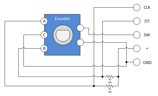
According to:

http://henrysbench.capnfatz.com/henrys-bench/arduino-sensors-and-input/keyes-ky-040-arduino-rotary-encoder-user-manual/

  • "+" is supply Voltage
  • "CLK" is Encoder Output A (with an included pullup R of 10k to "+" on the pcb)
  • "DT" is Encoder Output B (with an included pullup R of 10k to "+" on the pcb)
  • "GND" connects to both Encoder Output Common, and one leg of the push-button switch.
  • "SW" is the other leg of the push-button switch.

This next image is from the same website: http://henrysbench.capnfatz.com/henrys-bench/arduino-sensors-and-input/keyes-ky-040-arduino-rotary-encoder-user-manual/ http://henrysbench.capnfatz.com/henrys-bench/arduino-sensors-and-input/keyes-ky-040-arduino-rotary-encoder-user-manual/

The encoder is a typical quadrature style encoder with a an additional push-button in the knob stem.

So:

  • Connect 5V (or your existing system voltage) to the "+" input.
  • Connect your system ground to the "Gnd" terminal.
  • Connect the "CLK" terminal to one digital input.
  • Connect the "DT" terminal to the other digital input.

Confirm its all working with a voltmeter, then start writing code.

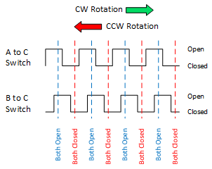
CLK and DT wavforms (image from the same web site noted above).

On the plot:

  • C = Ground
  • A = CLK
  • B = DT
  • "Open" = 5V output (measured with voltmeter).
  • "Closed" = 0V output (measured with voltmeter).

enter image description here

http://henrysbench.capnfatz.com/henrys-bench/arduino-sensors-and-input/keyes-ky-040-arduino-rotary-encoder-user-manual/

The dotted lines show where the switch detents should be (however, I can't confirm this without having the actual encoder in hand). What this means is that when you turn the encoder, and it 'clicks', the encoder is designed to stop between clicks at these locations. Sometimes one 'click' is many counts. This depends on the encoder's mechanical design (how the detents mechanically line up with the output electrical changes), and the decoding algorithm. If you get more than 1 count per click, then divide the output in software.

Some notes:

  • The labeling of the PCB seems silly.
  • There are things that you'll learn about interfacing mechanical switches to micro-controllers that may surprise you. Research this. Check compatibility with the "QEI" module you use - as I am not familiar with it.
  • For troubleshooting, I'd recommend that you define in your code these variables: CurrentCount, PreviousCount, DividedCount (%), Direction (CurrentCount - PreviousCount).
\$\endgroup\$
14
  • \$\begingroup\$ Oddly, the other schematic on that page shows no pull up resistors when connected to an Arduino. Are they actually needed? \$\endgroup\$
    – 19172281
    Commented Jun 22, 2018 at 16:05
  • \$\begingroup\$ The pull-up resistors are included on the encoder pcb. You do not need to add them. They're not shown in the second schematic because that schematic shows how to connect the encoder PCB to an Arduino, and the PCB already has the resistors installed. \$\endgroup\$ Commented Jun 22, 2018 at 17:11
  • \$\begingroup\$ Ahh, ok. I've made the connections you listed, and the mbed seems to be responding. However, 1 turn of the encoder seems to move the lit led by 2, and sometimes not at all. Does my code look sound to you? I also noted when using a voltmeter that as I turned the encoder, the measured. voltage remained at 5v \$\endgroup\$
    – 19172281
    Commented Jun 24, 2018 at 20:02
  • \$\begingroup\$ I suspect the double movement might have something to do with the X2 encoding. Still doesn't explain the missed counts. I should point out that I measured voltage from the CLK output to ground. \$\endgroup\$
    – 19172281
    Commented Jun 24, 2018 at 20:18
  • \$\begingroup\$ > "voltage remained at 5v... ...measured voltage from the CLK output to ground." - Well, that's not right. Both CLK and DT should have waveforms like shown above (edited answer). After looking at the QEI code, I think that you should use X4 encoding. What mbed board are you using? \$\endgroup\$ Commented Jun 25, 2018 at 12:24

Your Answer

By clicking “Post Your Answer”, you agree to our terms of service and acknowledge you have read our privacy policy.

Not the answer you're looking for? Browse other questions tagged or ask your own question.