I am preparing for an exam and I have a problem with the following exercise (hope my translation is good enough):
We have an op-amp circuit with gain \$G=+1V/V\$ for AC signals and \$G=0V/V\$ for DC. The op-amp has two power supplies. The input resistance (for medium-range AC signals) is \$50k\Omega\$. Assume that additional capacitors (if needed) are infinitely large.
The input signal - square wave with duty cycle \$50\%\$, has \$V_{pp}=50mV, \ f=1MHz\$ and offset \$ 5V\$.
Op-amp parameters: \$A_0=10^5V/V, \ f_{UG}=2MHz, \ I_+=I_-=2\mu A, \ SR=2V/\mu s\$
- Draw a diagram of the circuit, calculate every resistance
- On one graph, draw \$v_{in}(t)\$ and \$v_{out}(t)\$
- Calculate time \$t_x\$ which passes from the moment when output signal reaches \$-20mV\$ to the moment when it reaches \$+20mV\$
First question: is information about input bias currents important?
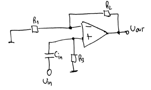
Secondly, I think that the circuit will look like this:
And here, for medium-range AC signals \$R_{in}=R_3=50k\Omega\$
In this circuit \$G=1+\frac{R_2}{R_1}=1V/V\$, hence \$R_1=+\infty\$
And since \$R_3\$ is a compensating resistor and it sees only \$R_2\$, then we got: \$R_2=R_3=50k\Omega\$
Because the amplitude of the input signal is equal \$50mV\$, then there is a possibility that SR effect can occur. We need to check it. \$A_{in}=A_{out}=50mV\$
I am not sure about English naming, thus:
\$f_{UG} \ - \ \text{Unity Gain, open loop} \\ f_{CL} \ - \ \text{-3dB point, closed loop} \$
And we have:
\$f_{CL}=\frac{f_{UG}}{G}=f_{UG}=2MHz\$
So:
\$A_{out}\cdot2\pi\cdot f_{CL}=50mV\cdot2\pi\cdot2MHz\approx 0.63V/\mu s < SR=2V/\mu s\$
There will be no SR effect.
Rise time:
\$t_r=\frac{0.35}{f_{CL}}=175ns\$
\$10\%\cdot50mV=5mV\$
Hence, \$t_r\$ is the answer for question no. 3.
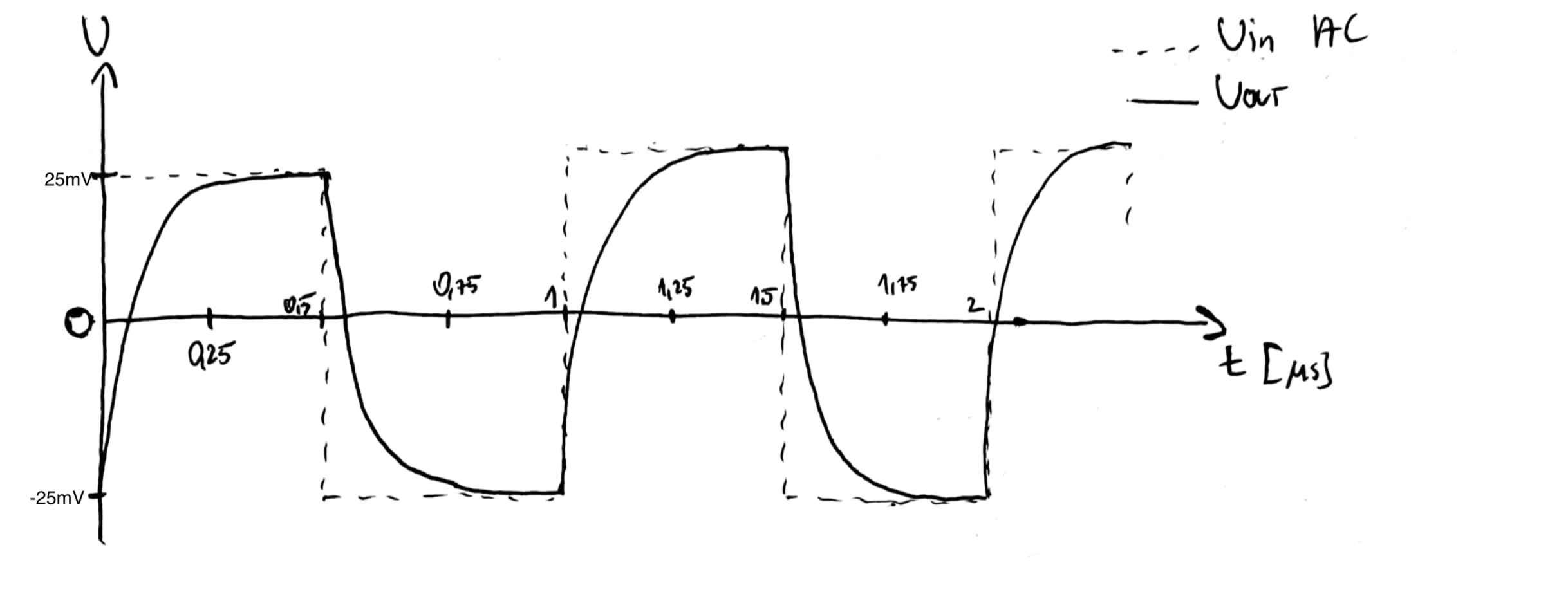
And the graph, I think it will look like this
Is my solution correct?


