1
\$\begingroup\$

I don't understand how to calculate the voltage that should enter the inverting terminal of the amplifier[V-] Could you help me to find out how this circuit works and why the output, when Vin is zero, will be 1.6V?

Note that \$R_1\$ and \$R_2\$ are a simple voltage divider, so we could remove those resistors to keep the circuit simple.

$$R_3 = 1\text{k}\Omega$$

$$R_4 = 3\text{k}\Omega$$

$$R_5 = 1.5\text{k}\Omega$$

CV+ (Positive supply voltage of the op amp) = +5V

CV- (Negative supply voltage of the op amp) = -5V
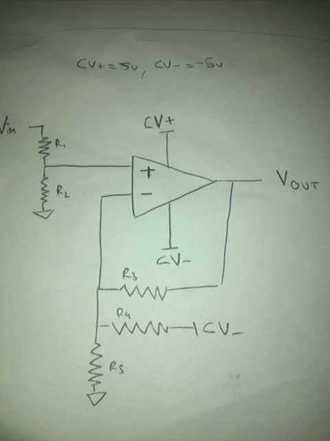
Op amp differential circuit

\$\endgroup\$

2 Answers 2

0
\$\begingroup\$

Feed back will try and make the two inputs the same. So the inverting input is also at zero volts. The negative voltage (CV-) is sucking 5/3k = 1.66mA from that node. The only place that current can come from is the opamp output. You need 1.66 mA flowing through R3... and that gives 1.66V on the opamp output. (No current can come from R5 because both sides are at zero volts... that is only true when Vin is zero.)

\$\endgroup\$
6
  • \$\begingroup\$ Thank you! But what happens if Vin is, for example 3 v or -2.5v ? And how can you solve that node of resistors? :) \$\endgroup\$ Commented Apr 22, 2015 at 10:34
  • \$\begingroup\$ If Vin is different from zero then you have more currents to sum at the inverting node. Why don't you write down the answer for Vin = 3V. \$\endgroup\$ Commented Apr 22, 2015 at 12:49
  • \$\begingroup\$ Ok, please tell me if I am right: The Kirchhoff's Current Law say that the current entering a junction is equal to the current exiting that junction. So, I suppose that the current trough resistor R3, which comes out from Vout is entering the node and so the sum of current through R4 and R5 must be equal to the current through R3. Vout/R3 = CV-/R4 + Vin/R5 Note that I supposed that the voltage across R5 is Vin - GND = Vin - 0v = Vin. As result: Vout = Vin/1.5 - 1.66. Am I right? \$\endgroup\$ Commented Apr 22, 2015 at 20:11
  • \$\begingroup\$ @user3424077 It doesn't look quite right. (Check your Vin = 0 answer.) Feed back forces the voltage at the inverting input to be Vin, so the current through R3 (for instance) is (Vout-Vin)/R3.. or (Vin-Vout)/R3, depending on which way you draw the current. \$\endgroup\$ Commented Apr 22, 2015 at 23:18
  • \$\begingroup\$ Ok, can you confirm me that no current ideally enter the inverting terminal? If so, the sum of the various currents entering and leaving the node will be zero, right? So the final equation will be: (Vin-Vout)/R3 + (Vin-GND)/R5 + (Vin-CV-)/R4 = 0. Thank you for all the patience you have with me! :) \$\endgroup\$ Commented Apr 23, 2015 at 14:05
0
\$\begingroup\$

To answer your first question, the non-inverting input, V+, is:

V+ = Vin[R2/(R1+R2)]

and the inverting input must be at the same voltage, ie V- = V+

The equation for Vout is easily found by nodal analysis at the V- node.

\$\endgroup\$

Your Answer

By clicking “Post Your Answer”, you agree to our terms of service and acknowledge you have read our privacy policy.

Not the answer you're looking for? Browse other questions tagged or ask your own question.