0
\$\begingroup\$

I'm working on a simple project to learn electrical circuits. I built a little sound box that will play tones when you press buttons.

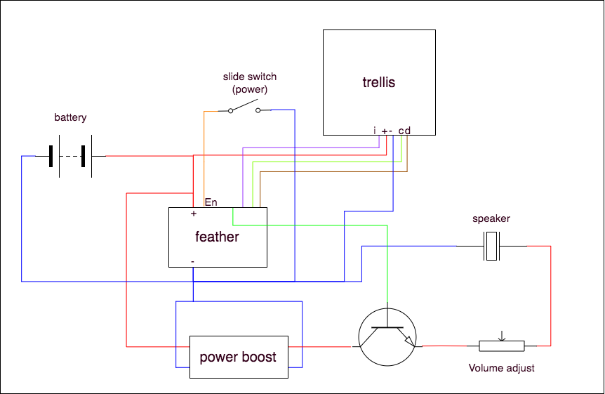
simple wiring diagram

The battery provides 3volts and the "power boost" is a buck converter that increases the voltage to the 9v needed to power the speaker.

I wanted to include a potentiometer to adjust the volume so I used one I had on hand. The problem was that most of the range of the potentiometer provided so little voltage that no sound came out of the speaker and then right as you get towards the end the volume shoots up.

I read a bit online and it seemed like using an analog potentiometer would resolve the issue since the resistance changed exponentially instead of linearly.

I swapped out the potentiometers, but it seems like I'm running into the same problem: most of the range of the potentiometer's resistance the voltage is so low that no sound comes out of the speaker.

I was talking with a friend and mentioned the issue and he suggested using a voltage divider to map the desired voltage range along the potentiometer. This sounds sensible, but I have no idea how it should be implemented.

Does using a voltage divider to map the voltage range to the speaker make sense? If so, how would I do it? I've been searching around for things like "potentiometer with a voltage divider" and "mapping voltage on a potentiometer" and have found plenty of results, but not for the task I'm trying to accomplish.

Any suggestions? Helpful links?

\$\endgroup\$
1
  • \$\begingroup\$ you connected the "volume adjust" variable resistor as a fixed resistor .... you have to connect to the wiper and to one of the ends of the resistor \$\endgroup\$
    – jsotola
    Commented Jul 15, 2018 at 19:12

2 Answers 2

1
\$\begingroup\$

It appears that you are using the potentiometer incorrectly for two reasons:

  1. You are using it as a variable resistor instead of a potentiometer.
  2. You have it on the speaker line. You should have it before the amplifier.

schematic

simulate this circuit – Schematic created using CircuitLab

Figure 1. (a) Rheostat. (b) Potentiometer. (c) Volume control.

Your diagram doesn't show the resistance value of the potentiometer or the speaker but let's say they are 1k and 8 Ω. 1k is a huge resistance to put in front of an 8 Ω speaker and only a small fraction of the power will get to the speaker. It's only when you decrease it to < 100 Ω that you can probably hear any change.

For a volume control we use a potentiometer. Note in Figure 1b that this has the bottom terminal connected to circuit ground. That means that as we slide the wiper up from the bottom the output voltage will vary from 0% to 100% of whatever is coming in on the IN terminal. (The output will actually be somewhat less if you have a load connected to the wiper. It will be very much less if you tried to connect your 8 Ω speaker to the wiper.)

What you need to do is get a proper amplifier circuit and hook it up as shown in (c). This way the volume control only has to deal with low powered signals and the amplifier boosts these to drive the speaker directly. That's how all amplification systems do it.

You need to draw proper schematics (component symbols, part numbers, designations - R1, R2, etc.) to help you and others understand your circuit. There are many online free tools and there is a CircuitLab button on the editor toolbar on this site (that I used for Figure 1). Have fun.

\$\endgroup\$
1
  • \$\begingroup\$ Oh nice!! I'm going to dig into this answer tonight to really grok it. Thanks for posting this! \$\endgroup\$ Commented Jul 16, 2018 at 14:44
0
\$\begingroup\$

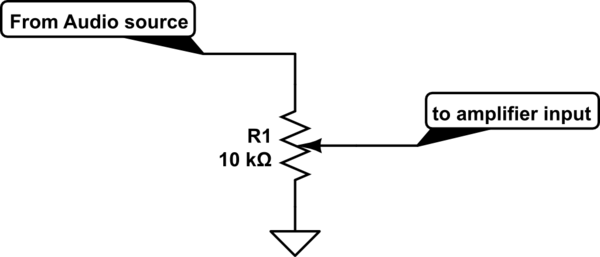
A volume control is generally wired as a voltage divider, like so:

schematic

simulate this circuit – Schematic created using CircuitLab

It is hard to say how this should be done in your situation, without a proper schematic of the audio portion of the circuit.

\$\endgroup\$
1
  • \$\begingroup\$ I'll try to get a better schematic drawn up. I'm still pretty green so I'm still learning to draw them. It looks like that CircuitLab site is going to be a really good resource for it thought! \$\endgroup\$ Commented Jul 16, 2018 at 14:44

Your Answer

By clicking “Post Your Answer”, you agree to our terms of service and acknowledge you have read our privacy policy.

Not the answer you're looking for? Browse other questions tagged or ask your own question.