13
\$\begingroup\$

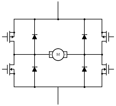
I'm currently learning about driving a small DC motor (~ 5V). My research so far indicated that a L298N might be a good choice to quickly get something up and running. However, I'm also trying to understand what is exactly happening (i.e. the internal H-bridge) and there is something which isn't really clear to me. The example circuit in the datasheet on page 6 uses four flyback diodes in a configuration that seems to be common for H-bridges (since other sites recommend similar H-bridge circuits). The configuration, neglecting the L298N for a moment, essentially looks like this:

Now, if I understand it correctly, these diodes provide a path for the motor to keep the current flowing when the MOSFETs get switched off to prevent large voltage spikes. The path for this current however seems to go right through the power source in the reverse direction. That is, reversed relative to the direction of the current that a power source normally supplies. This is indicated in the figure below.

Since I'm relatively new to the world of electronics, this seems like a weird thing to do. I get that this works on paper if the power source is a ideal constant voltage source. But is this actually safe in real life? Let's say I'm using a few alkaline batteries to power my project, then this reverse current seems like recharging. And the Wikipedia page about alkaline batteries says:

Attempts to recharge may cause rupture, or the leaking of hazardous liquids which will corrode the equipment.

Or what if I'm using a lab power supply or even a voltage regulator as a voltage source? How these reverse current are handled doesn't make a lot of sense to me and I'm worried that I might blow up my equipment.. Could somebody enlighten me about why the circuit above is actually safe? And if it isn't safe, then why are a lot of sites recommending it and what circuit should I use instead?

\$\endgroup\$
1
  • 4
    \$\begingroup\$ FYI, There are battery chargers on the market that are supposed to work with disposable alkaline cells. Some claim that you can re-use an alkaline cell dozens of times. Others say two or three times. YMMV. But, what I'm saying is, an alkaline battery will not instantly burst the moment it sees negative current. \$\endgroup\$ Commented Jul 20, 2018 at 17:18

4 Answers 4

13
\$\begingroup\$

The diodes serve two distinct purposes.

  1. Under regenerative braking, they return the generated voltage to the power supply (where with suitable electronics, it can be used to recharge the battery). Note that unless the motor is being run above its normal speed, the generated voltage will be no more than the supply voltage, so it is within the voltage rating of the power supply. So the power supply can normally withstand this - but if it can't absorb current (either to charge a battery, or dump it into a braking resistor) there will be little or no braking effect.
  2. The diodes also return inductive spikes (from the motor brushes) to the supply, and these may be hundreds of volts, for a very short duration, which can prove destructive to power supplies. Then to answer the actual question - the supply CAN be damaged by high voltage spikes, so its designer must take precautions to prevent that damage - like an inductor (ferrite bead) in series, and ample decoupling capacitors across the supply, and possibly a transient suppressor or varistor to absorb HV transients

Note there isn't generally enough energy in these spikes to do any damage whatsoever to a primary cell, so relax if you're connecting the bridge straight to a battery. But regulated supplies that aren't designed to drive motors may be a problem.

\$\endgroup\$
11
\$\begingroup\$

If the motor is producing power, the net power into the motor must be positive, so the net current out of the batteries must be in the direction that drains them, so you are fine.

If the motor is being regeneratively braked, then power can flow out of the motor and can push the supply voltage up and charge the batteries (this is used to advantage in electric vehicles). It's not something you generally need to worry about with a small motor connected directly to primary cells, but if you have a supply that cannot sink current (eg. a rectifier + filter) it could cause issues if the capacitor isn't large enough.

\$\endgroup\$
5
  • 1
    \$\begingroup\$ Thanks for your quick answer, I think I'm starting to get it. Thus one of the functions of the capacitor between +Vs and ground in the datasheet circuit is to provide a path for the current to flow in case the supply can't sink current? I'm asking this because my initial understanding was that this was just a smoothing capacitor that could safely be left out (as it is on the figure with the purple path). So if the supply can't sink current, the cap is absolutely necessary as to not damage the supply since the current then flows through the cap rather than through the supply. Is that correct? \$\endgroup\$
    – s1m0n
    Commented Jul 20, 2018 at 17:45
  • \$\begingroup\$ You absolutely need the capacitor and the leads should be short. You want to keep the loop area (and thus inductance) small or the MOSFETs can be damaged. \$\endgroup\$ Commented Jul 20, 2018 at 17:47
  • 3
    \$\begingroup\$ It is important to never use an LDO on a full bridge because they can only source + current and not sink . \$\endgroup\$
    – D.A.S.
    Commented Jul 20, 2018 at 21:47
  • \$\begingroup\$ @TonyEErocketscientist Thanks for the extra clarification. But I can still safely use an LDO on a full bridge if the capacitor is sufficiently big, right? \$\endgroup\$
    – s1m0n
    Commented Jul 22, 2018 at 10:04
  • \$\begingroup\$ Yes dV=Ic dt/C but it may need to be an ultra cap depending on tolerance of dV or a battery \$\endgroup\$
    – D.A.S.
    Commented Jul 22, 2018 at 12:12
1
\$\begingroup\$

Am not very familiar with motors, but will hazard an answer here. When modeling electrical circuits, say with SPICE, or similar package, the DC power supplies are usually modeled as short-circuits to ground. This is usually explained somewhat briefly in textbooks on elementary electrical engineering.

Recall also that a DC power supply will generally employ capacitors across its output, usually for the purpose of smoothing out ripple. These capacitors act as "shorts to ground" for transient currents.

\$\endgroup\$
0
\$\begingroup\$

Normally the high side drivers are used for direction on brush motors or stepper and BLDC pole switching while the low side for PWM to limit current, torque and acceleration.

When the low side driver turns off the voltage rises and current continues as it decays with a short to V+ so current does not circulate thru the battery or supply when turned off. It continues on the high side driver and the opposite motor polarity high side diode.

This alternates with polarity and direction in the same fashion blocking the current to the supply as it continues to circulate thru the opposite driver until several L/R time constants .

\$\endgroup\$

Your Answer

By clicking “Post Your Answer”, you agree to our terms of service and acknowledge you have read our privacy policy.

Not the answer you're looking for? Browse other questions tagged or ask your own question.