5
\$\begingroup\$

This is more of an academic exercise than something practical. I've uploaded the image from a solution manual to a problem I was working on. I can't seem to agree with what they've done.

Also I can't seem to find a Euler path that works for both PUN and PDN.
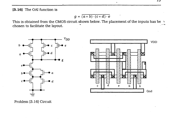
Anyways about their solution, the PDN doesn't make sense to me. Why is the a/b shared region connected to Gnd? How are e/d/c connected? And how is b connected to g? Only e could be connected to g in the PDN according to their circuit diagram. Also I'm unsure if their Euler path (which looks like c,d,e,a,b) works for the PUN.

Anyways if someone wants to offer their own solution instead of trying to explain this one to me that would be fine as well.

EDIT - No longer interested in trying to understand/fix the given solution, it seems to have too many bugs. I am interested in seeing someone's worked-out solution (xtor schematic and stick diagram layout) to the given function: g = NOT((a+b)(c+d)e)

\$\endgroup\$
6
  • \$\begingroup\$ a b to ground is already a flag... if there was a well, maybe. \$\endgroup\$
    – pat
    Commented Aug 28, 2012 at 22:37
  • \$\begingroup\$ So I'm not crazy in assuming something's wrong here? I could do the last few exercises (similar 4-input AOI functions) without much trouble. \$\endgroup\$
    – JDS
    Commented Aug 28, 2012 at 23:02
  • \$\begingroup\$ Maybe there was a typo on lettering. I'm not going to troubleshoot, but yes, it does not look right. g(out) is connected to devices, a, d, and e in schematic..a,b,c, and e in layout. \$\endgroup\$
    – pat
    Commented Aug 28, 2012 at 23:10
  • \$\begingroup\$ There are 3 abbreviations in this question and I know none of them. Explain unusual abbreviations when you use them. \$\endgroup\$ Commented Aug 29, 2012 at 11:26
  • \$\begingroup\$ Pull Up Network (PMOS portion of circuit), Pull Down Network (NMOS's). Gnd is ground. AOI logic is made of and/or/invert. \$\endgroup\$
    – JDS
    Commented Aug 29, 2012 at 16:34

2 Answers 2

3
\$\begingroup\$

NO you're not crazy. According the schematic the only NMOS that should be connected to node "g" is one of the S/D's of "e".

Also, the NMOS active cannot be one piece as drawn and there need only be one ground connection.

\$\endgroup\$
3
  • \$\begingroup\$ Yeah, I'm going to update the OP. I don't care about trying to figure out or correct the solution manual, I just want to see someone's worked-out answer since I can't seem to do it myself. \$\endgroup\$
    – JDS
    Commented Aug 29, 2012 at 21:15
  • \$\begingroup\$ Assuming it isn't a homework problem, wouldn't it be more helpful to work on exercises without errors? \$\endgroup\$
    – pat
    Commented Aug 29, 2012 at 21:32
  • 2
    \$\begingroup\$ !layout \$\endgroup\$ Commented Aug 29, 2012 at 22:36
4
\$\begingroup\$

It's been a few years since I last did this kind of thing, so I thought I'd try to figure it out.

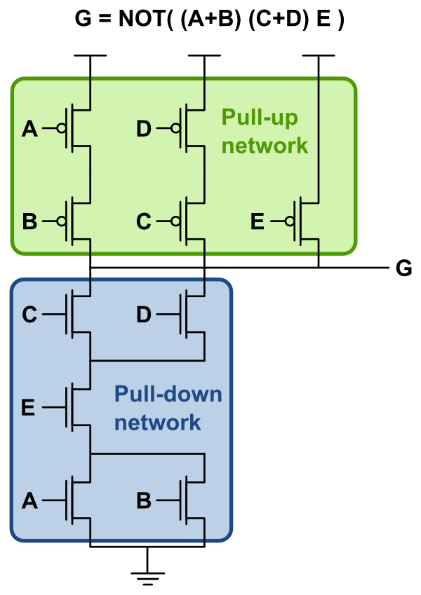
Here's the transistor diagram: enter image description here

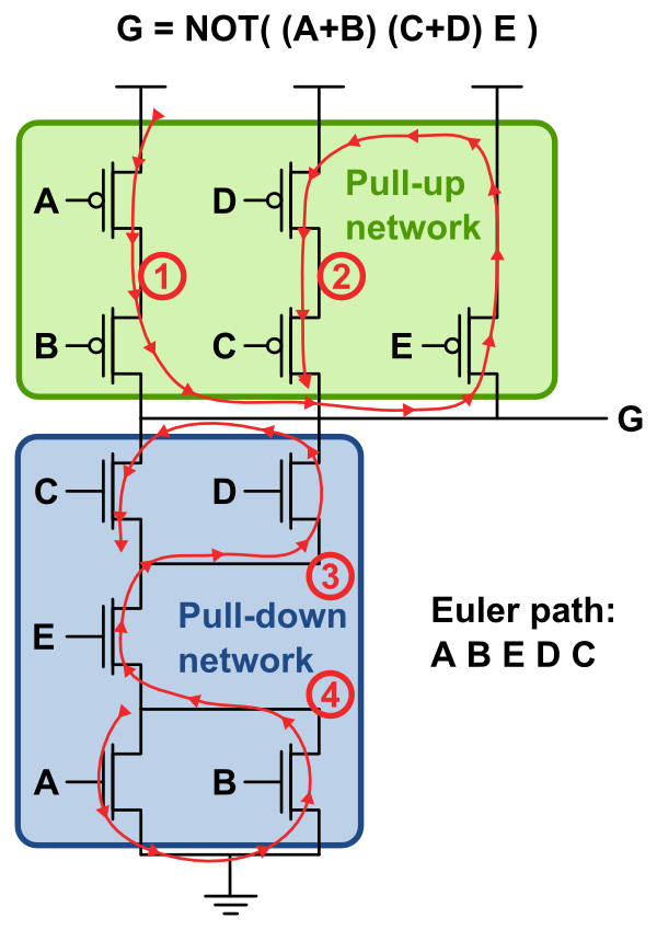
Here's the transistor diagram with the intermediate nodes labeled 1-4, and with the Euler path drawn in for both the PUN and PDN: enter image description here

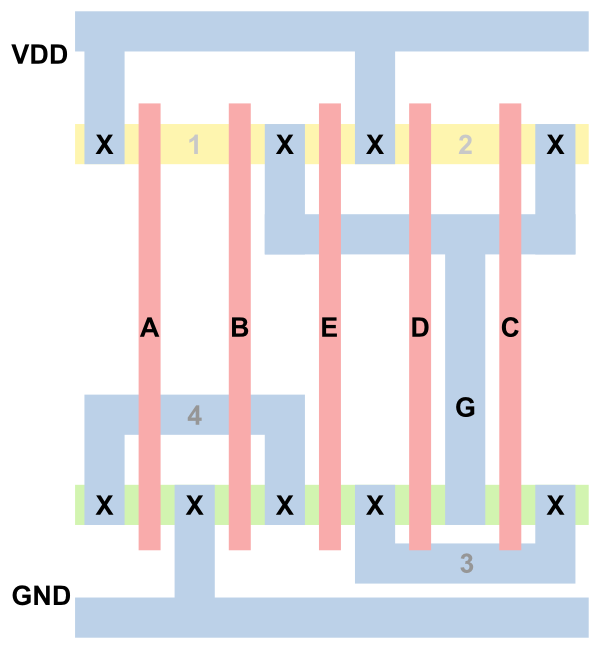
Here's the stick layout: enter image description here

\$\endgroup\$

Your Answer

By clicking “Post Your Answer”, you agree to our terms of service and acknowledge you have read our privacy policy.

Not the answer you're looking for? Browse other questions tagged or ask your own question.