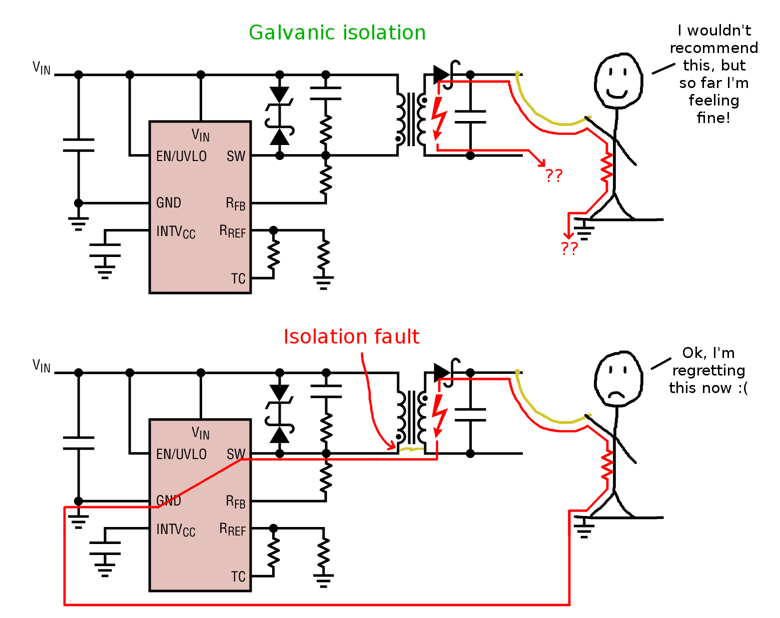
Is it correct to say that the primary reason to have galvanic isolation (ensuring minimum clearance and creepage distance for required voltage of power circuit between HV and LV) between the HV power circuit and low voltage control circuit is to eliminate the possibility of creepage current or static discharge between the two?
-
\$\begingroup\$ No, that sounds like a very special reason. What is HV power circuit more specifically in your application? \$\endgroup\$– winnyCommented Sep 29, 2018 at 19:13
-
\$\begingroup\$ Example: HV circuit would be buck converter with 1000V as input voltage and LV circuit is current control circuitry \$\endgroup\$– AutobotCommented Sep 29, 2018 at 19:23
-
1\$\begingroup\$ Where does the 1000 V come from? What’s the minus rail referenced to? \$\endgroup\$– winnyCommented Sep 29, 2018 at 19:55
-
\$\begingroup\$ 1000V comes from a floating power supply meaning minus rail is not connected to earth ground. \$\endgroup\$– AutobotCommented Sep 29, 2018 at 21:25
-
\$\begingroup\$ Then you already have galvanic isolation from the mains. \$\endgroup\$– winnyCommented Sep 30, 2018 at 7:06
2 Answers
- galvanic isolation means
- having no direct conductor path between a potential voltage difference
- it provides insulation breakdown threshold to a reasonably safe level defined by IEEE, and international safety bodies
- where the primary protection from lighting are grid lightning arrestors, then 8kV arrestors built into residential electric meters.
- then power supplies are designed to meet these local standards based on international standards
- a line filter attenuates voltage spikes,
- possible MOV, TVS or fused gas-tube voltage clamps provides additional overvoltage protection (OVP) for insulation breakdown between conductors with galvanic protection
- the threshold for 10us spark breakdown is about >=3x the AC line frequency and DC breakdown threshold with some exceptions below due to the ionization time required. The best galvanic isolation may be optocouplers for their low pF coupling in a wide body with an air gap underneath for typical applications, not all.
it does not mean;
- it is HIPOT protected if the user say "earth-grounds floating DC outputs" while the Mfg tests HIPOT with floating outputs.
- I discovered 10 major causes of failure in this mode from one supplier who moved product to Mexico after I DVT qualified their product, yet it was US process engineer's and ultimately the QA Mgr's fault. Earth bonding increases capacitance E field stresses in insulation vs floating which couples the ferrite CM capacitance back to HV sources.
- If it passes HIPOT, it will never fail in the lightning capital of Florida.
static conduction is eliminated
- the user or Test Engineer of a major corp must perform ESD and HiPOT tests under worst-case conditions to validate the design and process
- the customer must beware of dust humidity and maintenance neglection issues
- dust + moisture = mobile ions of charge between a potential difference if the flow accelerates and conducts enough a fault may occur.
eliminates the risk of data errors from noise,
even 1m USB so-called balanced differential lines, get corrupt connections with a galvanically isolated supply connected to an earth bonded tower PC. This occurs often when long peripheral cables are connected to the mobile SMPS powered device acting as an antenna for ingress and egress and poor CMRR on a std short USB2 cable.
This reduces air from 1k~3kV /mm down to 500 typ to ?100V/mm in extreme cases which has an industry standard contamination environment level. You can make it down to 10V/mm if there is salt spray if I recall.
- Partial Discharge (PD) oscillations like a ticking geiger counter are the precursor to corona depending on contamination level of insulation medium. (every year major oil-filled grid-transformers around the world blow up due to this often, preventable fact due to lack of monitors.)
The main reason for galvanic isolation between an HV circuit (say mains) and an LV say (perhaps touched by people) is the safety of the people from electric shock.
-
\$\begingroup\$ I mean, I understand that ofcourse safety is an underlying reason. But what I meant was, safety could be compromised because a. without galvanic isolation both HV and LV circuit are connected and HV can transfer on LV side causing safety issues and b. with galvanic isolation, not ensuring required clearance and creepage distance, static discharge could lead to similar situation. Isn't that correct? \$\endgroup\$– AutobotCommented Sep 29, 2018 at 19:22
-
\$\begingroup\$ It wouldn't be static as there is a power supply involved. It's real leakage current. \$\endgroup\$ Commented Sep 29, 2018 at 20:35
-
\$\begingroup\$ So, let's say then if we have a galvanic isolation for 500V and we apply 1000V, ofcourse there would be a path from HV to LV side via real leakage as you mentioned. But it be sustained flow of charge from HV to LV only because we have an unlimited supply of charge from power supply ( speaking ideally ofcourse), but if it would have been battery, then it would have been a similar case like lightning, right? ie.. flow until charge is balanced?? \$\endgroup\$– AutobotCommented Sep 29, 2018 at 21:30

