0
\$\begingroup\$

I'm using an arduino Leonardo clone (SS Micro) who works on 5V logic only, but has also a 3.3V output for powering devices.

I'm interfacing it with a breakout board TOF sensor, the VL6180. This board has 2.8V logic, but has level shifting on the SCL and SDA lines, so it can be powered from 5V from Arduino, and connected directly to SCL and SDA pins on arduino, because it converts the I2C signals from Arduino 5V logic to 2.8V logic (on the VL6180) and back from it's 2.8V to Arduino 5V.

The problem I have is that there's an interrupt pin on this breakout board, GPIO1, that can be programmed to generate output interrupts, but this pin is not level shifted. So it outputs 2.8V or 0V. And it's internally pulled high, so when an interrupt is generated it goes low (0V). When idle it's high (2.8).

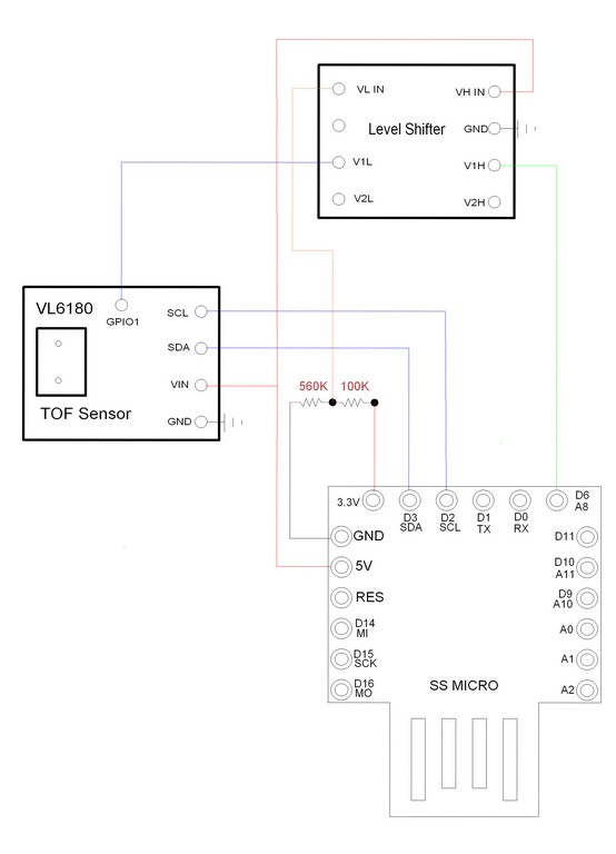
As this Leonardo clone I have has 3.3V output just for powering devices (not logic levels), I used this 3.3V output with a voltage divider circuit (2 resistors) to achieve 2.8V. So I connected this 2.8V line, from the voltage divider, to a level shifting breakout board on the low side, the 5V from Arduino on the High side. And I connected the GPIO output from the sensor (at 2.8V) to a low side channel on the level shifter board, and an Arduino digital input pin (at 5V) to the same channel, but on the high side of the level shifter.

So it would convert the 2.8V signal from the sensor to arduino input pin, at 5V.

But it doesn't work. The sensor generates the interrupt. I can confirm (using a multimeter) that when the interrupt is triggered on the sensor it's GPIO1 pin goes from 2.8V to 0V. But in the 4 channel level shifter breakout board, the 5V on the other side remains unaltered. It's always 5V. I tried changing between the 4 channels on the level shifter and still no change on the high side (5V never goes to 0 volts)

I tried connecting instead the 3.3V out pin from the Arduino directly on the low side of the level shifter, without the voltage divider circuit, but it didn't work either.

There is a 2.8V source somewhere in this sensor breakout board, but in my board there's no soldering pad to a 2.8V line, and unfortunately my sensor is already mounted inside a casing with silicone all around it, so I can't remove it to try to find a track where I could use it's own 2.8V voltage.

So.. My guess is that using only this voltage divider isn't enough for providing a 2.8V reliable source for powering the level shifter and to make it work correctly.

What should I do to achieve a realiable 2.8V source so I can use it to make this level shifter work correctly?

My enclosure is really small, so too many extra components or extra boards wouldn't fit inside. Schematics
\$\endgroup\$
7
  • 4
    \$\begingroup\$ Voltage dividers are notoriously poor designs for power supplies. They are subject to wide variations in output depending on the load current. Can you try an LDO regulator? \$\endgroup\$
    – mike65535
    Commented Oct 5, 2018 at 15:42
  • 5
    \$\begingroup\$ Voltage dividers are already a poor fit for this, additionally the shown resistors are several orders of magnitude too large. But then the level shifter device is not really meant for this purpose; it is designed for bidirectional signals and so needs a low side supply that isn't otherwise needed in your application. If you could tolerate inversion, using an NFET with the gate driven by the low side would be a simple solution, working against pull-up on the 5v MCU side. \$\endgroup\$ Commented Oct 5, 2018 at 16:02
  • 1
    \$\begingroup\$ Check the specs on your Leonardo's inputs - you may well find that 2.8V is 'high enough' so be registered correctly on an input and you wouldn't have to do any level shifting. \$\endgroup\$
    – brhans
    Commented Oct 5, 2018 at 17:41
  • \$\begingroup\$ @Chris Stratton: I have a NFET here. No problem in inverted logics. So I would have to wire the gate directyl to the 2.8V output of the sensor board. But forgive me my ignorance, as I'm a new learner in electronics, but how would I wire the source and drain, in relation to the input pin in arduino? Thanks for this simple solution. \$\endgroup\$
    – Rodrigo
    Commented Oct 5, 2018 at 20:44
  • \$\begingroup\$ @brhans It seems that for the Leonardo working at 5V, from 1.9V beyond would be detected as High. So, could I connect My GPIO1 from the sensor (from 0 to 2.8V) directly to the arduino input? Should I leave the arduino input floating or pulled down to 0V? As the sensor board at the GPIO1 pin logic is inverted, it's always 2.8V when idle, and when the interrupt occurs, it goes to zero volts. So my code should detect a fall in the input, not a rise. Is that correct? \$\endgroup\$
    – Rodrigo
    Commented Oct 5, 2018 at 21:03

2 Answers 2

1
\$\begingroup\$

A VL6180 board must have a stable 2.8V power supply (locally, at least the Sparkfun board has it), otherwise the sensor will have goofy unstable results. You need to use this rail to feed the low side of your interrupt level shifter instead of weak voltage divider.

Or you can try a diode in series to drop the VL_IN voltage from 3.3 into 2.6-3.0 area instead of resistive divider (replace your 100k with a 1N4148 diode).

And you will need a pull-up to 5V on the high-side of level shifter.

ADDITION: per suggestion of brhans, the min input level for ATMEGA32U4 is 0.2Vcc+0.9V = 1.9V, while even a fully loaded (8 mA) interrupt output from VL6180 should produce 2.4V, so no need in the level translator at all.

\$\endgroup\$
4
  • \$\begingroup\$ Hi! Thanks! My board doesn't have this VDD 2.8V pin as others have. It's so tiny. I even found the line on the voltage regulator CI, but is so so small I'm afraid ruining it trying to solder it... I'll try the diode to see if it works... Thanks! \$\endgroup\$
    – Rodrigo
    Commented Oct 5, 2018 at 20:38
  • \$\begingroup\$ Thanks! I've seen that too! Should I pull low externally the arduino input pin, in this case? \$\endgroup\$
    – Rodrigo
    Commented Oct 5, 2018 at 21:18
  • \$\begingroup\$ @Rodrigo, no other pulls is necessary, it seems that your VL6180 board does have the necessary PULL-UP. According to VL6180 datasheet, the interrupt pin is "open drain". Pull the net low will destroy the whole idea. \$\endgroup\$ Commented Oct 5, 2018 at 21:53
  • \$\begingroup\$ I just tested connecting the boards GPIO1 out directly to the Leonardo’s input and it worked perfectly. Thanks a lot for all the fast responses for all you guys! \$\endgroup\$
    – Rodrigo
    Commented Oct 6, 2018 at 1:38
-2
\$\begingroup\$

A faulty design usually follows bad assumptions and no interface specs that must be done 1st. Avdd=2.6 to 3.0V

There are no links in your question. , no scope traces, result tables and comparison of specs vs results in the question.

If you list these carefully and show test method if unsure. You may even resolve it yourself in the process.

Thanks.

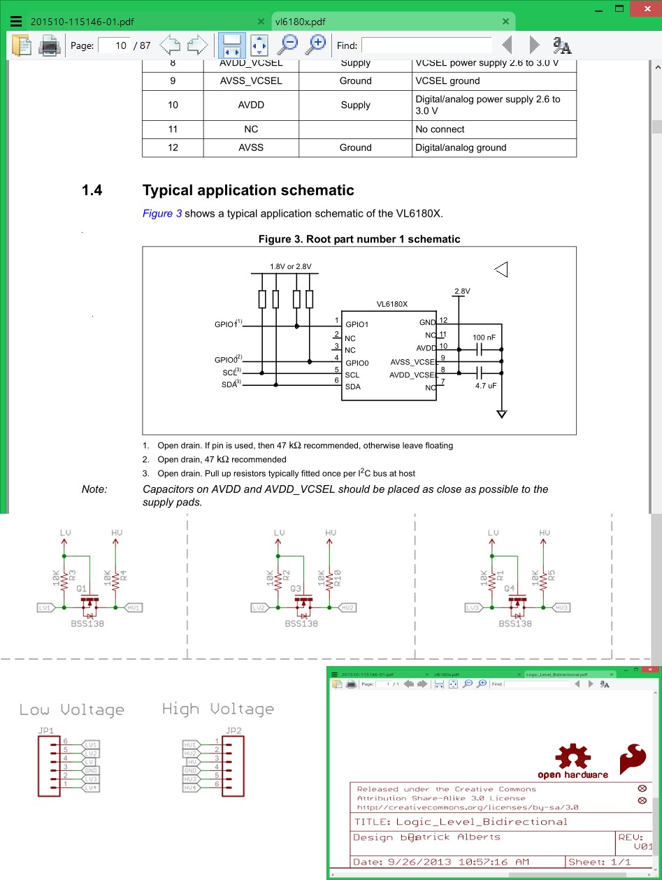
enter image description here REF https://www.sparkfun.com/products/12009

\$\endgroup\$
3
  • \$\begingroup\$ Hi Tony! Maybe you didn’t pay attention to what I wrote. I do have the datasheet for the sensor. That’s what I used to code the GPIO1 for arduino. I never wrote I wired to the sensor directly. I wrote I used a breakout board TOF VL6180 sensor. As I also wrote, in this board, there is a voltage regulator that converts 5V to the 2.8v logic it uses, back and forth on the SCL and SDA bus. As I also wrote, the GPIO1 pin on this board is not level shifted and already is internally pulled high, so this board also must have a resistor to pull both GPIO1 and GPIO0 (which I won’t use) pins high. \$\endgroup\$
    – Rodrigo
    Commented Oct 5, 2018 at 19:14
  • \$\begingroup\$ I see what you used . yet you have no datasheet interface specs or actual measurements in your question. So understanding your voltage discrepancy is really unclear. I see 5V to the Vin on board yet no specs in your question. is that my fault?. Focus on the performance error in voltages vs datasheet in question. with clear Spec vs error for each pin in a list format. \$\endgroup\$
    – D.A.S.
    Commented Oct 5, 2018 at 19:51
  • \$\begingroup\$ In the level shifter, I had to guess ! \$\endgroup\$
    – D.A.S.
    Commented Oct 5, 2018 at 19:59

Your Answer

By clicking “Post Your Answer”, you agree to our terms of service and acknowledge you have read our privacy policy.

Not the answer you're looking for? Browse other questions tagged or ask your own question.