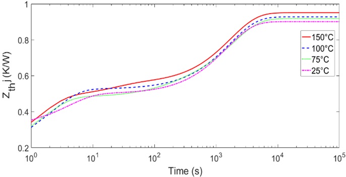
As shown in the picture below, thermal impedances of an IGBT device depends on the temperature. However, there is a strange phenomenon as follows. While with increasing the temperature, steady-state impedances will increase, but you can see that at a low time some low-temperature impedances become larger than high-temperature ones. Why? Note: We can model such impedances by resistor-capacitor circuits. Do we have the aforementioned phenomenon in RC circuits, namely lower value at a low time but higher value at a high time. How can justify this?
2 Answers
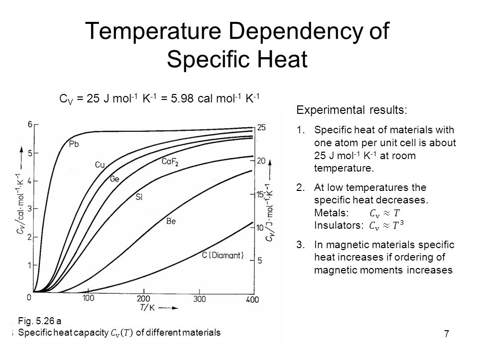
The graph you show (for short time durations) is governed by the specific heat capacity of the material in question. For longer/extended time periods it is governed by the thermal conductivity of the material. Specific heat capacity for most common materials (and possibly most uncommon materials) falls with temperature hence, at lower temperatures, a particular material will exhibit what your graph shows at short time durations.
If you want to find out more, examine the specific heat capacity for the material in the IGBT.
Do we have the aforementioned phenomenon in RC circuits
No, an RC model of the thermal properties of a material is not reflected in a change of capacitance - the model assumes that the thermal properties remain constant unless there is particular attention paid by the model designer to making capacitance change with local ambient temperature (I've never seen this done BTW).
Thermal impedance of an electronic device is a loosely specified parameter. The value depends on certain loosely-defined ambient air conditions and some "standard load" PCB, and published data usually represent the worst corner of design parameters. So designing a correct thermal management usually includes some substantial fudge factor, +20 - 30 %, if reliable cooling is thought.
The correct interpretation of the presented chart is that the particular device impedance doesn't depend on temperature to ANY SIGNIFICANT DEGREE, and these small crossings in lines should be safely ignored.


