0
\$\begingroup\$

The input signal to my board is an AC signal.

My board will process this signal. My board can handle 3.1Vpk-pk maximum without any damage occurring.

In the event that my input signal exceeds that I want to build a circuit that can stop (and hold or hold it at 0V if easier) the input to the board at 3.1Vpk-pk.

What I want to do: for signals in the range 0-3.1Vpk-pk they will pass through the circuit unaffected, for signals above this the output can be either a constant value or zero, which ever is easier to design. We can assume that the maximum voltage that could be supplied can go up to 20-30V while the typical input will be in the range 0-3.1Vpk-pk. The signal's frequency should be unaffected by this circuit.

I have been searching for days for protection circuits but cannot find any for an AC input signal which is unbelievable to me.

How to I go about designing and building this? My initial simulations included a unity gain buffer that would saturate at max input but this failed.

Any guidance to the name of this circuit or guidelines that can help me design one on my own will be great. Thank you.

\$\endgroup\$
3
  • \$\begingroup\$ Many overvoltage protection circuits are not specifically for any type of signal. This is just a signal input, and you don't intend to draw any power from it? You can probably use almost any type of generic input protection circuit (assuming you are ok with distorting the signal somewhat, which you have not really specified). \$\endgroup\$
    – Justin
    Commented Nov 1, 2018 at 19:24
  • \$\begingroup\$ I've stated that the frequency of the signal should not be affected. Can I have the names of those overvoltage protection circuits you speak of? \$\endgroup\$ Commented Nov 1, 2018 at 19:25
  • \$\begingroup\$ Well, the signal will probably no longer be a perfect sine wave. Though the fundamental frequency should be unchanged, there will be components of higher frequencies. This is unavoidable, though you can certainly specify the max distortion if this is a problem. A simple circuit would be a series resistor followed by a pair of TVS (transient voltage suppressors) or diodes, one to supply and one to ground. \$\endgroup\$
    – Justin
    Commented Nov 1, 2018 at 20:11

1 Answer 1

1
\$\begingroup\$

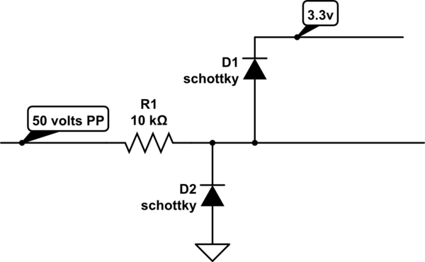
How about this? I've been assisting a Arduino-board developer, and he likes this to protect against 50 volts from a sensor

schematic

simulate this circuit – Schematic created using CircuitLab

Now, you need to think about the ADC's charge demands during the input sampling time. An extra 10Kohm will triple the settling time.

\$\endgroup\$

Your Answer

By clicking “Post Your Answer”, you agree to our terms of service and acknowledge you have read our privacy policy.

Not the answer you're looking for? Browse other questions tagged or ask your own question.