0
\$\begingroup\$

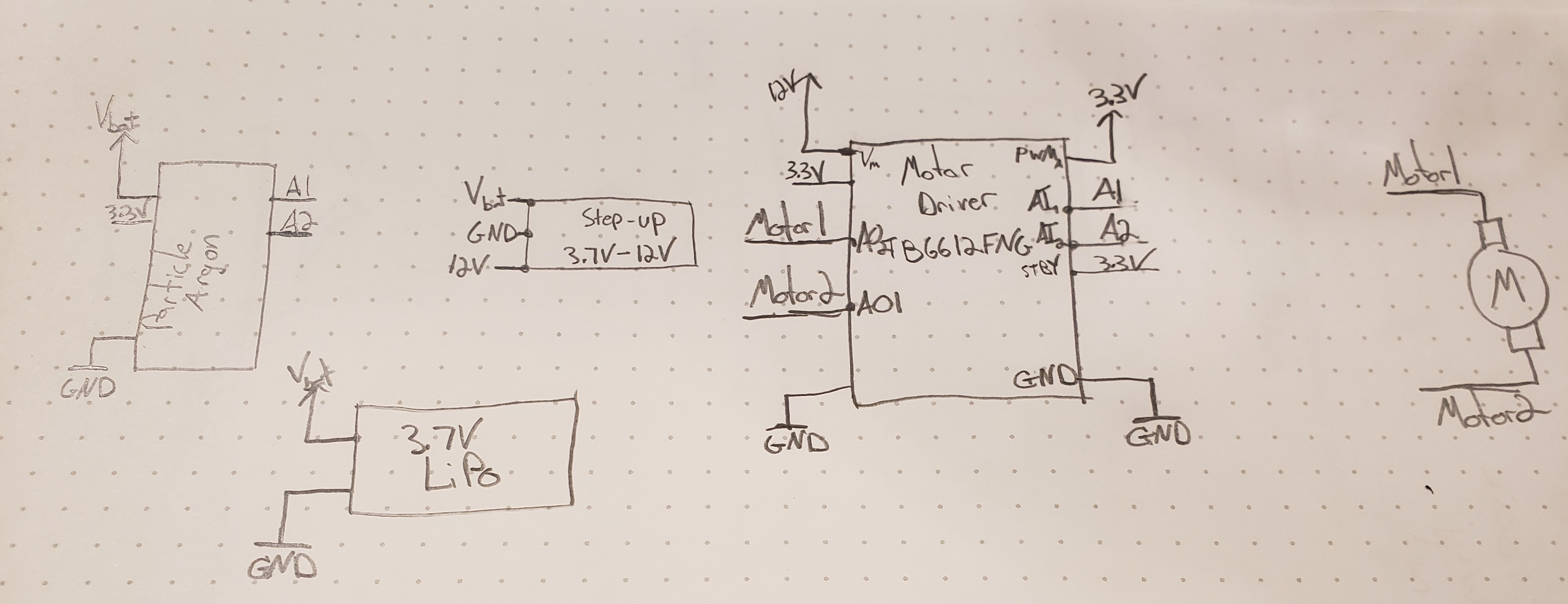
I am trying to control a 12V DC motor using a Particle Argon, powered by a 3.7V LiPo. To get 12V I am using this step up regulator, and to control the motor I am using this DC motor controller. I am also using the Particle Argon as my microcontroller with a typical 3.7V LiPo battery

I am able to control the motor at a lower voltage by dropping the duty cycle at the PWM pin, but when running (particular when changing direction or starting the motor), the Particle Argon resets.

I am assuming that the current surge required when powering the motor is causing the voltage at the microcontroller to momentary drop, thus resetting it. Any thoughts? Is there a better approach to accomplish this? Maybe a capacitor anywhere is the circuit to solve this problem?

Any insight would be GREATLY appreciated.

Schematic

\$\endgroup\$
6
  • \$\begingroup\$ Can you please provide links to the datasheets for the battery and the motor? These seem to be the critical components here. \$\endgroup\$ Commented Jan 17, 2019 at 1:04
  • \$\begingroup\$ Sure. The battery is a typical 3.7V 6500mAhr LiPo. Here is a link for the motor (well actuator): s3.amazonaws.com/actuonix/Actuonix+P16+Datasheet.pdf \$\endgroup\$
    – Greg
    Commented Jan 17, 2019 at 1:33
  • 1
    \$\begingroup\$ No, we really need a datasheet for the battery...I don't know what "typical" means to you. The actuator datasheet is actually for several models...which one are you using, and how is it mechanically loaded? \$\endgroup\$ Commented Jan 17, 2019 at 1:43
  • \$\begingroup\$ I am using the 256:1 actuator in the data sheet. No mechanical load now, just bench testing. Here is a link to the battery amazon.com/uxcell-6500mAh-Rechargeable-Lithium-Polymer/dp/… \$\endgroup\$
    – Greg
    Commented Jan 17, 2019 at 1:54
  • 1
    \$\begingroup\$ No, this is not a datasheet. We need something that specifies the maximum discharge rate. The vendor page does mention that this battery is not suitable for high-discharge applications, but I can't tell from what you have provided whether the battery is suitable for driving the actuator. \$\endgroup\$ Commented Jan 17, 2019 at 2:26

1 Answer 1

0
\$\begingroup\$

Your battery and step-up converter are not able to supply enough current for the motor.

To estimate how much current is needed, let's use the worst-case current required by the motor, which is the stall current of 1000mA at 12V. Depending on the load, the normal operating current looks like 100mA to 500mA, but I would expect a brief current close to the stall current when the motor starts.

So, if we need 1000mA at 12V, and we (unrealistically) expect 100% efficiency from the dc-dc converter, then you need 3000mA at 4V into the converter. This exceeds the maximum discharge current of the battery (by 3X) and also exceeds the maximum input current of the dc-dc converter (by over 2X). This is an optimistic estimate. It gets worse as the battery discharges and its voltage gets lower, and it gets worse if the actual efficiency of the dc-dc converter is considered.

So, bottom line, you need a much larger battery and a much more capable dc-dc converter. You might also consider using a separate battery for the actuator so the current surges don't affect the electronics.

\$\endgroup\$
1
  • \$\begingroup\$ All of that makes a lot of sense. Back to the drawing board! Thanks for breaking it down and for the help, Elliot. Very much appreciated! \$\endgroup\$
    – Greg
    Commented Jan 17, 2019 at 14:22

Your Answer

By clicking “Post Your Answer”, you agree to our terms of service and acknowledge you have read our privacy policy.

Not the answer you're looking for? Browse other questions tagged or ask your own question.