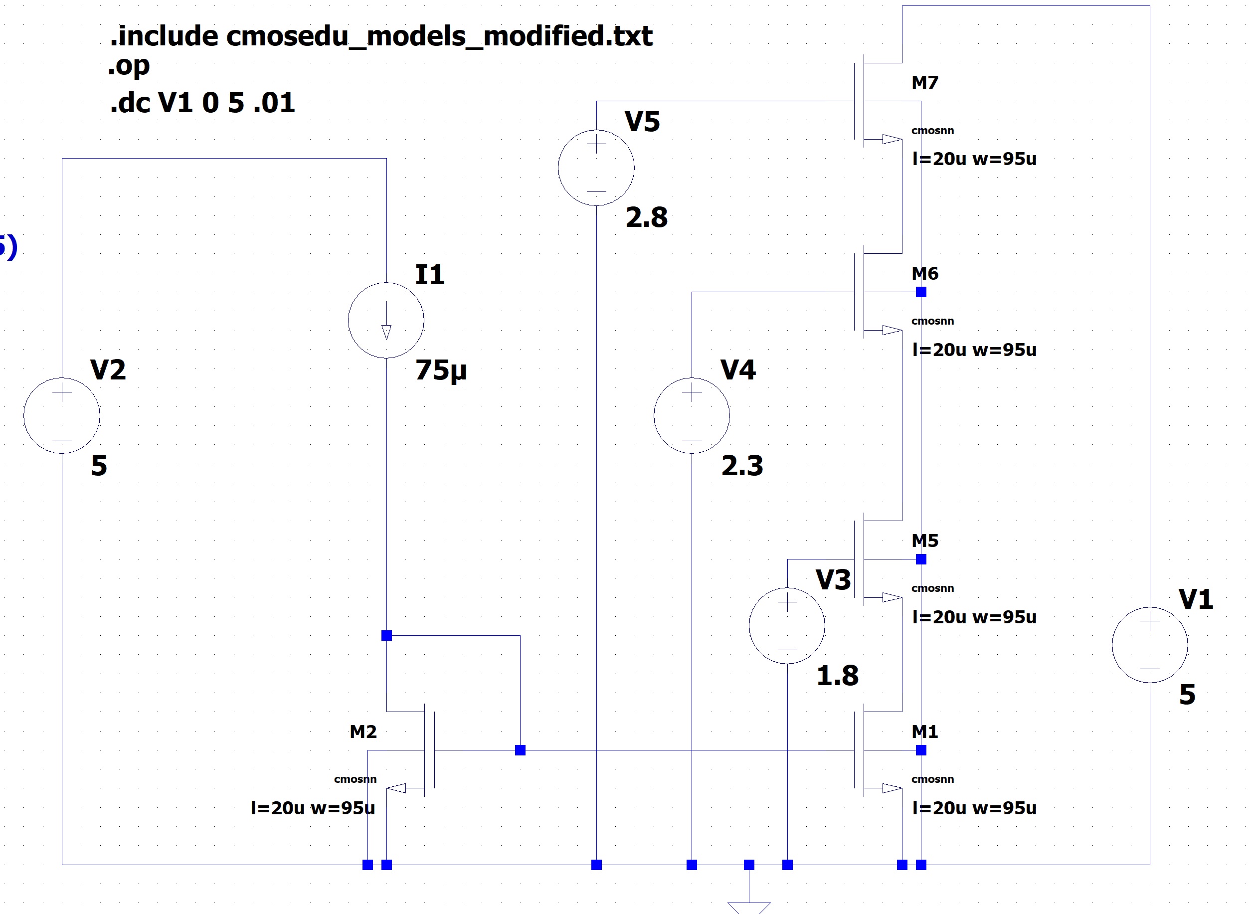
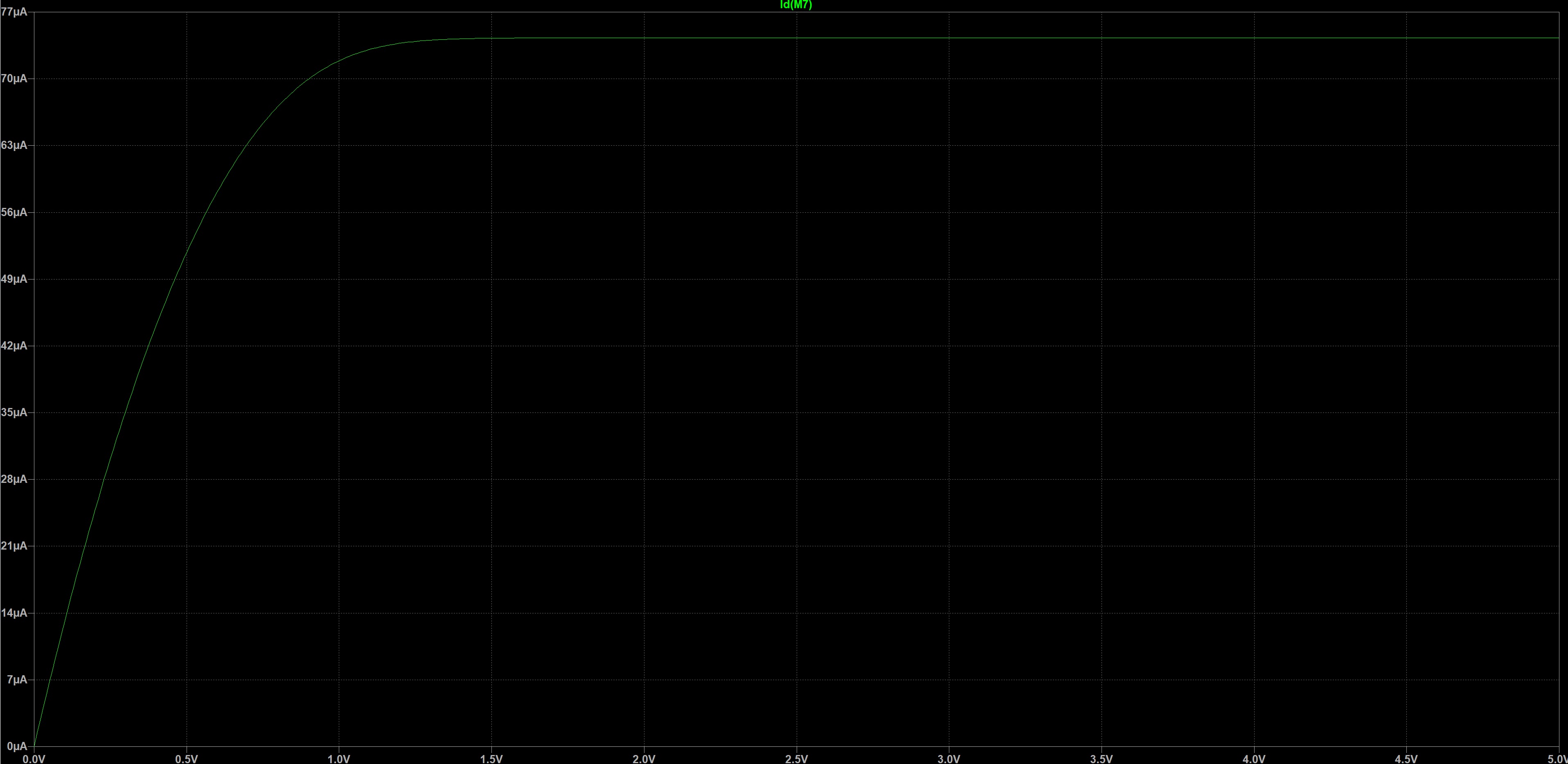
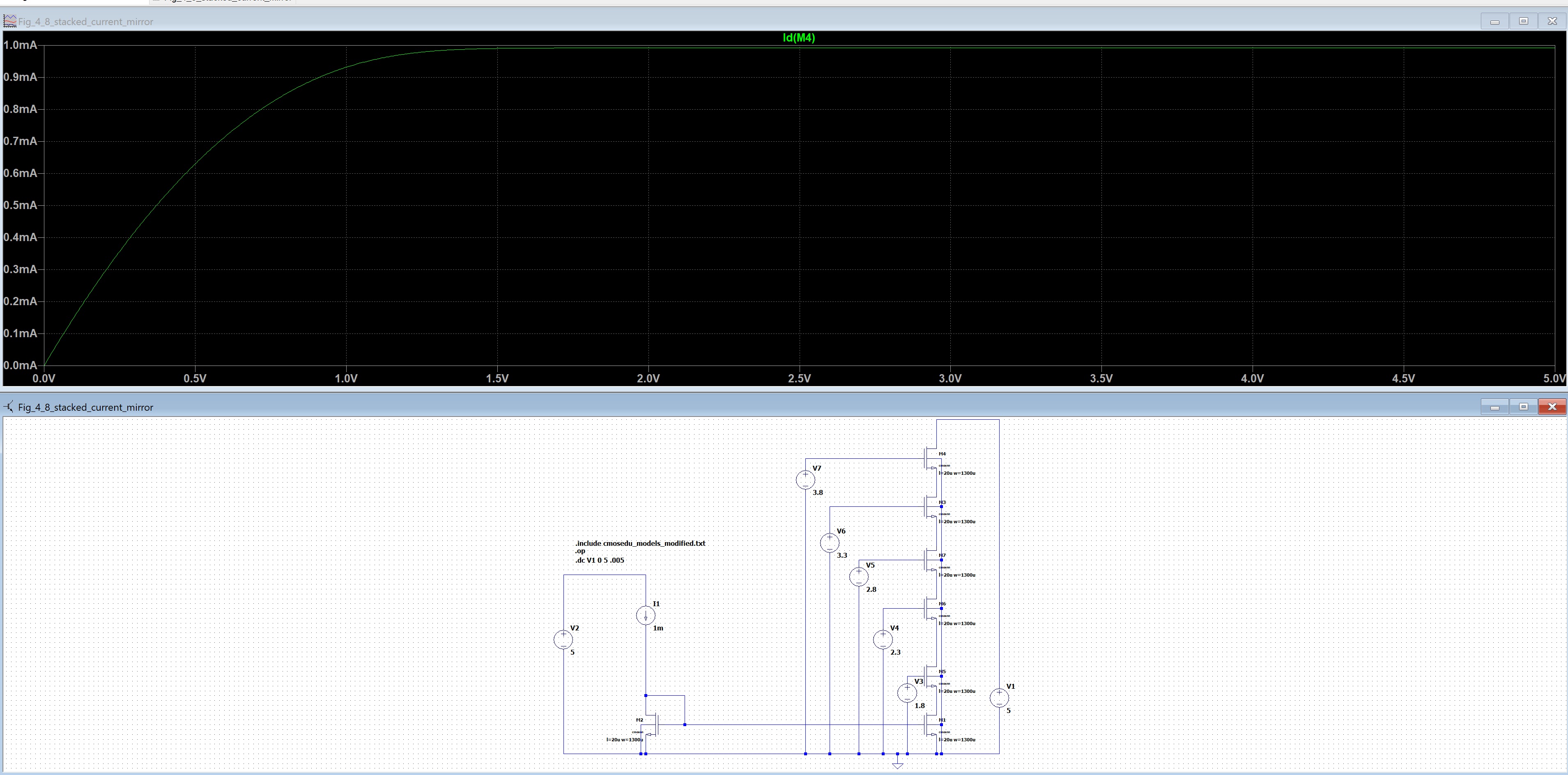
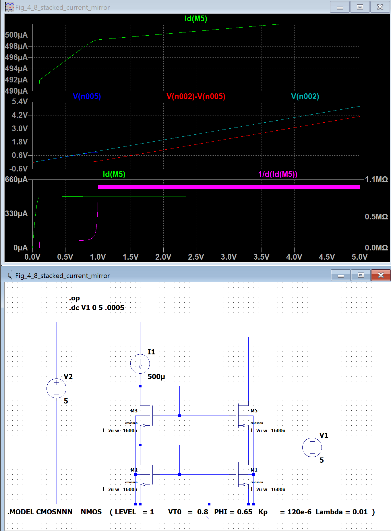
I am running a few very rudimentary cmos circuits in LTSPICE. For some reason, when designing stacked mirrors, I seem to get a much lower saturation turn on thresholds would be expected. I've tried many different combinations of short/long channel lengths and aspect ratios. In this case, I would expect a min vout of 4*(VGS-Vt) or 4*.5 = 2V, but the current gets saturated at the output at only about < 1.5V. When using smaller lengths, it goes even lower, like 2(VGS-VT) when the current should saturate at 4(VGS-VT).
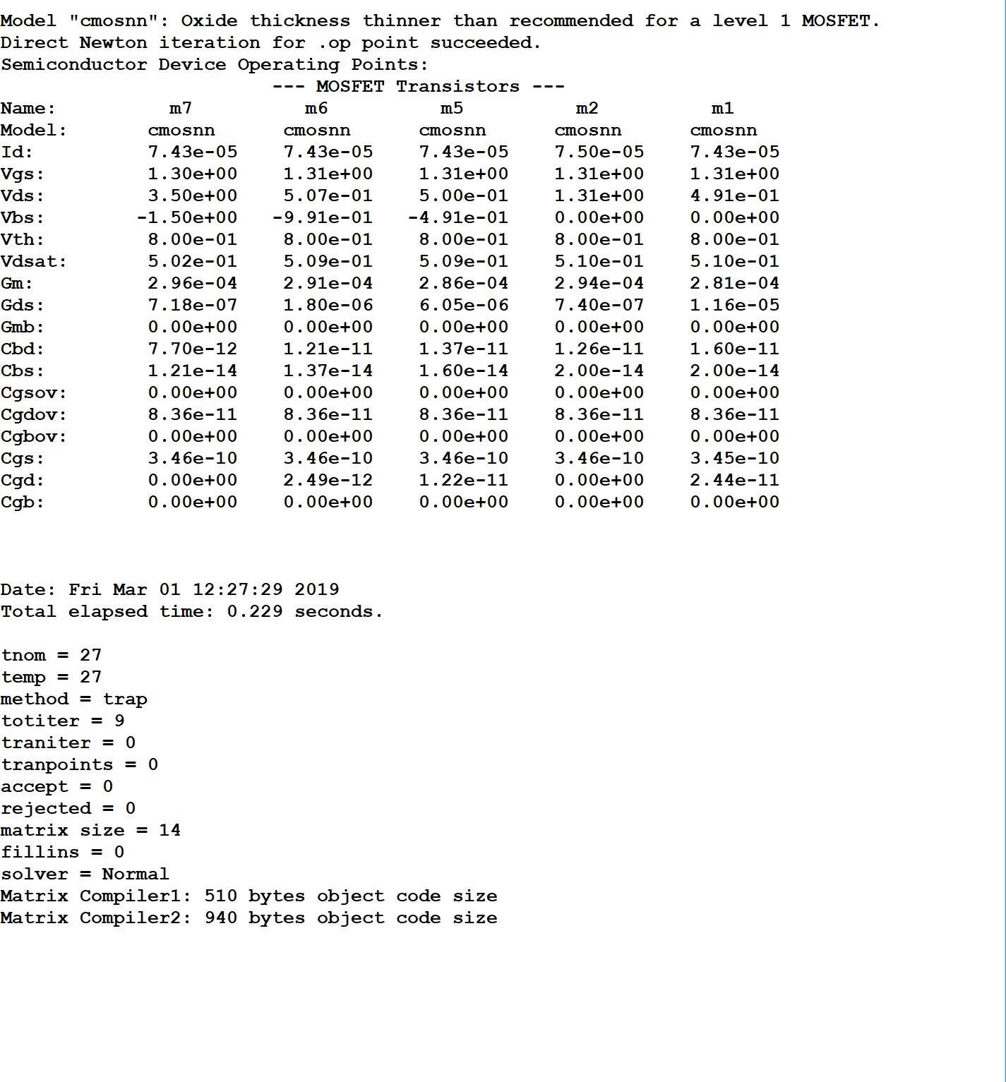
I'm using very simple level one models VTO = .8 and forced gamma to 0, to ignore the body effect. The spice operating points seem reasonable. The DC sweep saturation point, however, does not.
Several different stacked configurations are saturating way lower than expected.
Note: One device mirror only matches perfectly, it's when the transistors are stacked that the unexpected results occur. Also, the .op VDS are very slightly lower then VGS-VT, but I can tweak up and there's not much difference. I separated the Vdd sources, but results are the same with using only 1 Vdd source and sweeping output voltage. One other point, the number of matched diodes connected sources to the left (4), and the problem does not change at all. Current still saturates much lower than expected. It is understandable that models vary, etc... But the model deck has very simple models that mostly match expected 1st order level 1 calculations.
Here is a cascode stack of 6 devices, vdsat = vgs-vt = 0.5 I would expect 6*.5 = 3V min before devices saturate, but the dc sweep shows only < 1.5V.

