1
\$\begingroup\$

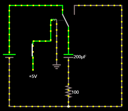
I have this simple circuit which uses a relay to charge and discharge a capacitor. Now instead of a mechanical switch, I want to use an electronic switch such as a N-Channel Mosfet.

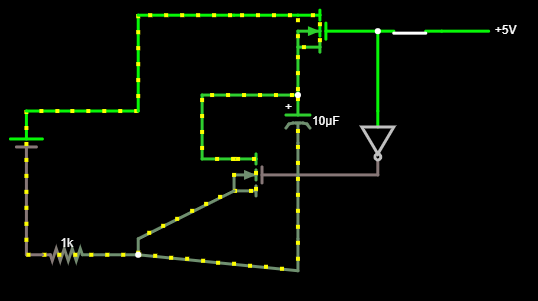
How can I replace the relay with a N-Channel Mosfet?

Original

My proposed solution so far:

Proposed solution

\$\endgroup\$
4
  • \$\begingroup\$ For a start, you'll need two switches - one to charge, one to discharge. \$\endgroup\$
    – Transistor
    Commented Mar 10, 2019 at 11:17
  • \$\begingroup\$ What's your source voltage? The gate voltage of the high side FET needs to be higher than that (by a margin that depends on the exact device) to turn it fully on. \$\endgroup\$
    – Hearth
    Commented Mar 10, 2019 at 14:22
  • \$\begingroup\$ Correct. I didn't edit the standard values in the software. But then it still is not replaced the way I wanted to, since the gate voltage with the switch is higher than the other voltage source. \$\endgroup\$ Commented Mar 10, 2019 at 14:29
  • \$\begingroup\$ @SparklingWater Put the FET on the low side instead of the high side then. \$\endgroup\$
    – Hearth
    Commented Mar 10, 2019 at 14:57

3 Answers 3

1
\$\begingroup\$

If the charge and discharge rates must be identical, then you are going to need to switch both the charge and discharge sides as shown by @Hearth. If they do not need to be identical, then there are a few alternate approaches.

The following is an example of using all N-channel devices to charge and discharge capacitor C1. C1 is charged through R2 when M1 is turned on, and discharged through R1 + R2 when M1 is turned off.
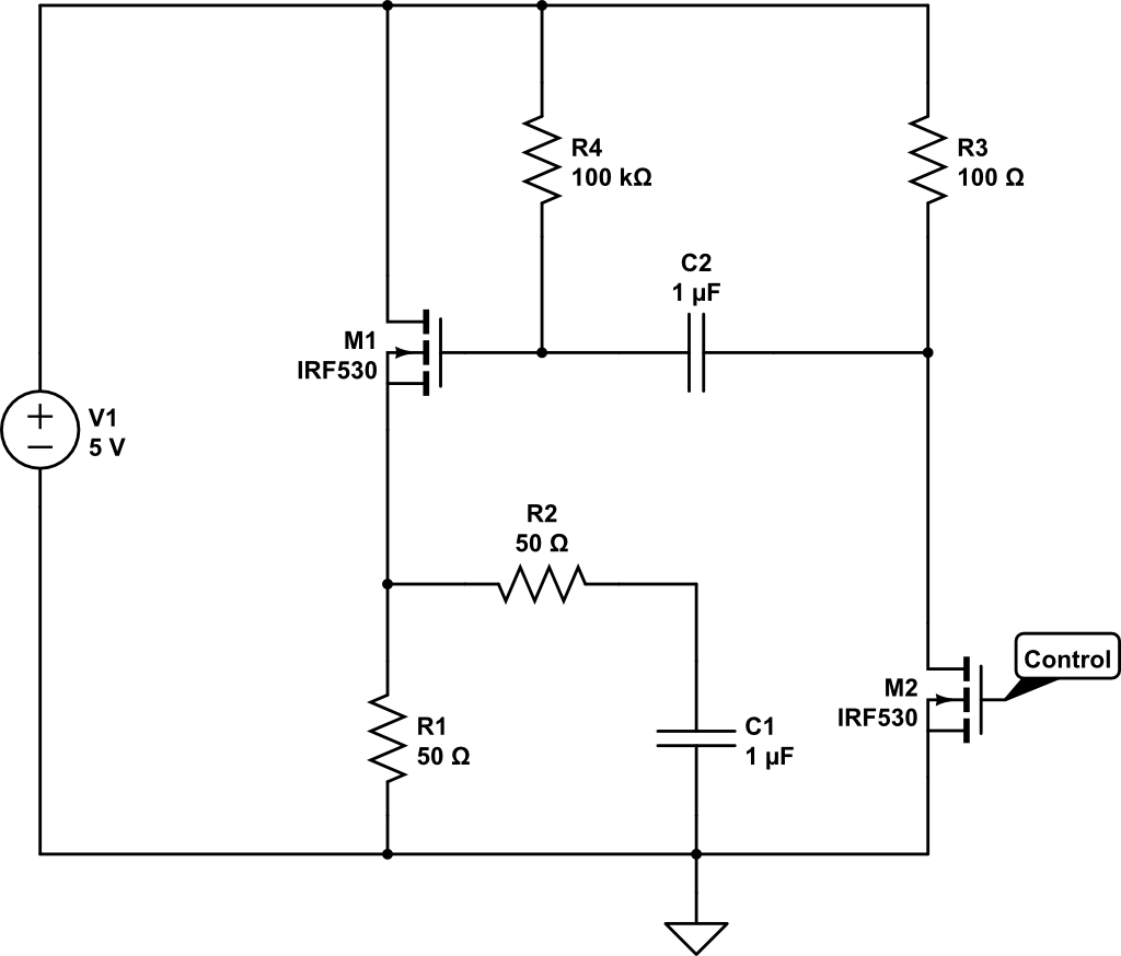
High-side switching with N-channel FET

M2, C2, R3, and R4 are used to 'charge-pump' the gate of M1, so that it can turn on even though there is no higher-voltage supply for switching M1.

How It Works:

Control is a 0V/5V signal. Low turns off M2. High turns on M2.

  • Start with Control LOW and M1 OFF.
    • C1 discharges to 0V through R1 + R2.
    • C2 'discharges' to 5V on both sides through R3 and R4.
  • Set Control HIGH
    • M2 is turned on
    • C2 is pulled to approximately ground (source-drain voltage of M2) on one side, and the other side charges to approx. 5V through R4.
      • When C2 is charged, it contains a stored charge of C x V == 0.1uF x 5V.
    • M1 remains off
  • Set Control LOW
    • C2 still has the stored charge 0.1uF x 5V.
    • C2 right-side charges towards 5V through R3.
      • At same time C2 left-side is 'pushed' to over 5V due to stored charge.
    • C2 left-side starts to discharge towards 5V through R4.
      • Discharge of left-side is slower than charge-up of right-side.
      • Current difference is 100k / 100.
      • Left-side of C2 discharges 1e3 times slower than right-side charges.
      • The stored charge is slowly drained off until both sides C2 are about 5V.
      • MEANWHILE...
    • M1 gate goes to about 10V and discharges towards 5V as left-side C2 discharges.
    • M1 turns ON.
    • C1 charges towards 5V through R2.
    • If you leave Control LOW long enough, eventually M1 gate discharges to cutoff and M1 shuts off.
  • Set Control HIGH
    • M2 turns ON.
    • C2 right-side gets pulled to ground(ish).
      • C2 has about zero stored charge.
    • C2 left-side gets pulled to about ground
    • M1 turns OFF if it is not already off due to leaving Control LOW too long.
    • C2 left-side begins to charge towards 5V through R4.

Lather, rinse, repeat. :)

Notes:

  • You must switch Control HI/LOW fast enough to keep M1 from turning off when the C2 'pump' voltage drops below M1's gate-source turn-on voltage.
  • You can play with R3/R4 to control the 'pump' time constant which impacts the required period for Control.

If you want C2 to recharge fast, you can add D1 in parallel with R4 as shown below. With this change, when control goes HIGH, C2 right-side is 'grounded' and C2 left-side charges "really fast" through D1 to 5V - 0.6V(ish, the forward-biased diode voltage). When Control goes LOW, D1 reverse-biases and C2 left-side discharges through R3 as in the first circuit.
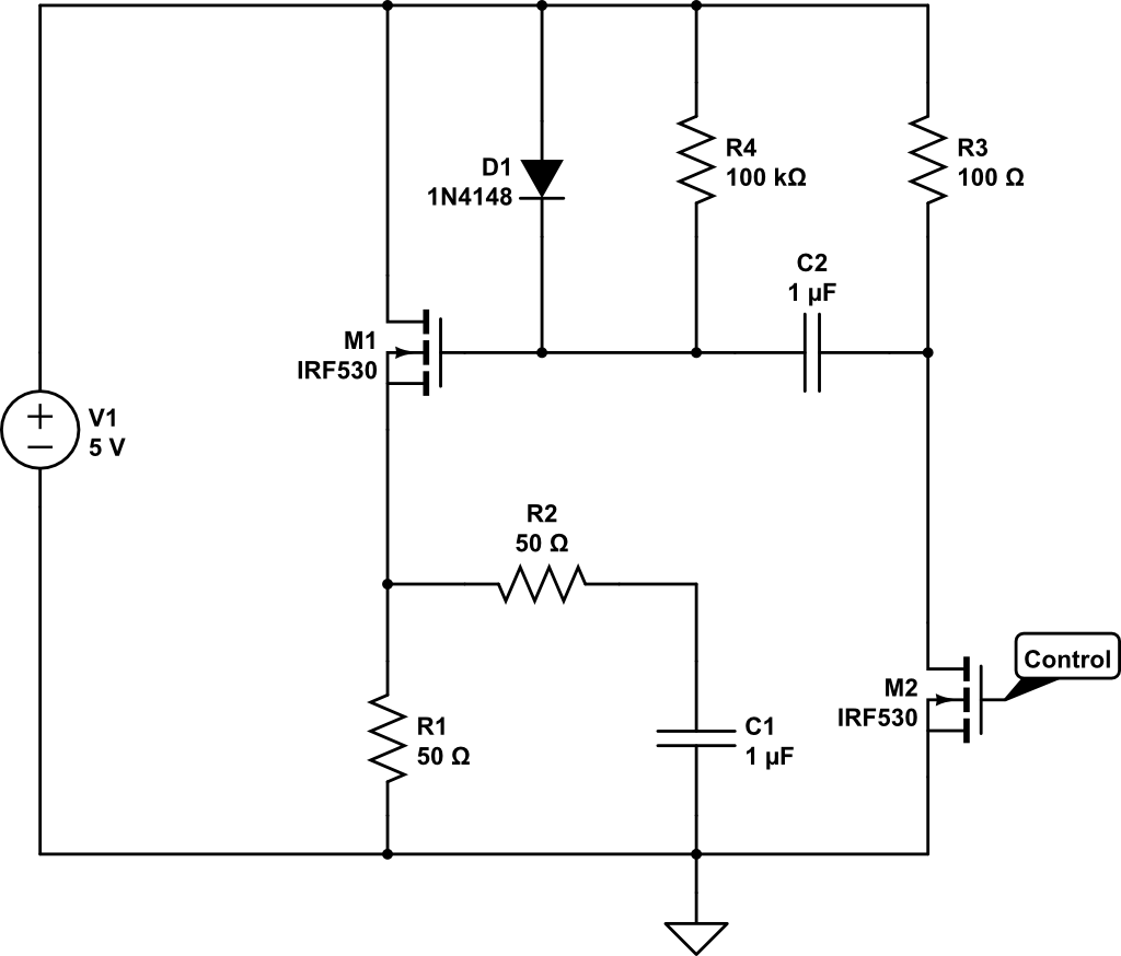
Diode-Assisted High-Side Switching

\$\endgroup\$
1
  • 1
    \$\begingroup\$ Thank you for the detailed description. I am rather interested in low power consumption when the Gate at M2 is low. Also compared to the relay in my example I think this one cannot be used to power an LED for example when discharging the capacitor because the LED would restrict the flow in one direction. The mechanical relay circuit is able to achieve that. I have no specific scenario in mind yet, so I am simply trying to have the solution as generic as possible. \$\endgroup\$ Commented Mar 11, 2019 at 16:40
0
\$\begingroup\$

When the cap is charged up, the upper FET's gate voltage has to be around 5 V greater than the cap peak voltage. If you are firm about using only n-channel FETs, you can solve this with a floating gate driver IC.

A more simple solution is to use a p-channel FET to charge and an n-channel FET to discharge. But this method has its own complications. There is a chance that both FETs will be on at the same time as the input signal transitions from one state to the other. This is called cross-conduction, or "shoot-thru". The standard solution here is small R-C delay networks to make sure one FET is off before the other comes on. However, you can limit the shoot-thru current by having two identical resistors, one for charging and one for discharging.

\$\endgroup\$
0
\$\begingroup\$

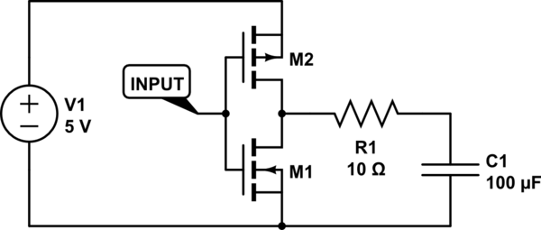
If you're open to using both p- and n-channel devices, a classic CMOS inverter might be the way to go:

schematic

simulate this circuit – Schematic created using CircuitLab

Can't get much simpler than that. If you want n-channel devices only, though, it's going to be a little harder and it's too early in the morning for me to figure out how best to do that without shorting your source right now.

Since you seem to be using circuitjs, here's a circuitjs implementation of exactly this.

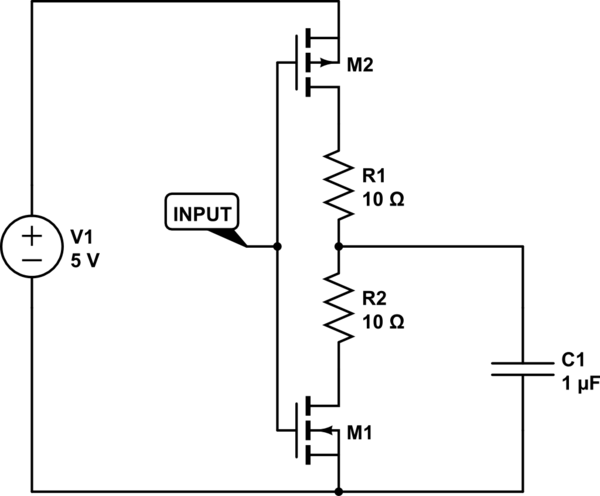
To account for the shoot-through problem that @AnalogKid brought up in their answer, you could also use two resistors arranged like so, which will limit the current when both transistors are on.

schematic

simulate this circuit

And for a bonus tip: if you want to invert the logic so the capacitor charges when the input is high and discharges when the input is low, just connect the capacitor to +5V instead of ground.

\$\endgroup\$

Your Answer

By clicking “Post Your Answer”, you agree to our terms of service and acknowledge you have read our privacy policy.

Not the answer you're looking for? Browse other questions tagged or ask your own question.