0
\$\begingroup\$

I'm trying to create an extension cord capable of measuring the power draw of devices connected to it. My approach is using a microcontroller with a non-invasive HWTC current sensor. I am using an ADS1015 12-bit ADC which is capable of converting up to 3300 samples per second. The microcontroller is programmed so that it finds the highest voltage peak flowing through the sensor (as I am measuring AC) and then I am calculating the RMS current.
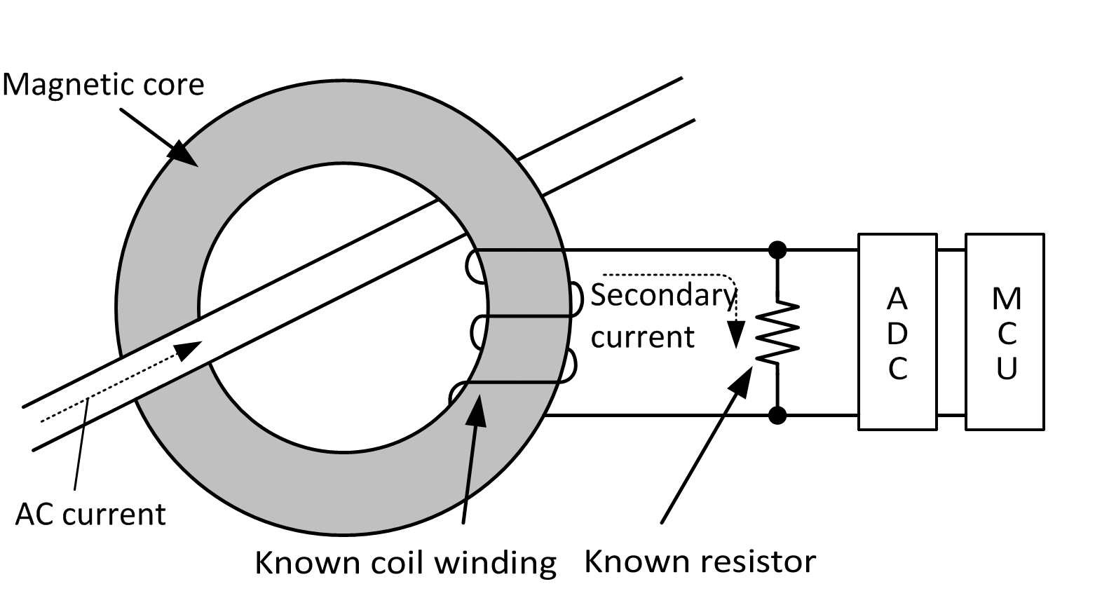
Simple schematics

This is a simplified code running on my MCU:

/// Gets the peak voltage over the next 500 ms
/// \returns Peak voltage in mV
float getPeakVoltage(ADS1015& adc) {
    Int16 maximum = 0;
    const Ulong start = millis();
    // Measure for 500 ms
    while ((millis() - start) < 500) {
        const Int16 value = adc.readDifferential();
        if (value > maximum) {
            maximum = value;
        }
    }
    // 1 bit from ADC = 3mV
    return static_cast<float>(maximum) * 3.0f;
}

const float peakVoltage = getPeakVoltage(adc);
// Using Ohm's law
static constexpr float resistorValue = 220.0;
const float peakCurrent = peakVoltage / resistorValue; // Sensor current ratio is 1000:1
const float powerDrawRms = 230.0 * peakCurrent * 0.707f; // in Watts

This approach works flawlessly for simple loads such as a Wolfram light bulb, however, when I connect, for example, a phone charger, it yields garbage. And by garbage, I mean way too high current draw.

Now I, unfortunately, don't have an oscilloscope to see what the waveform looks like, nonetheless, why my approach fails with different loads attached to the sensor?

\$\endgroup\$
2
  • 1
    \$\begingroup\$ ”I, unfortunately, don't have an oscilloscope to see what the waveform looks like” That will make it near impossible to troubleshoot. \$\endgroup\$
    – winny
    Commented Apr 4, 2019 at 21:05
  • \$\begingroup\$ @winny So you think the general approach is correct? Because I think there must be something wrong with my approach. Something is telling me, it's not gonna be that easy as I thought it would be. \$\endgroup\$
    – ProXicT
    Commented Apr 4, 2019 at 21:14

2 Answers 2

1
\$\begingroup\$

I believe your problem is that you are assuming the current waveform is sinusoidal since you are taking only the peak value and then calculating the RMS value. In practice, since many devices use switching power supplies, the current waveform will not be sunusoidal and may have large peaks. Since your ADC can sample fast enough, you should take many more samples over one or more cycles of the input current waveform (either 50 or 60 Hz) and calculate the RMS value from them.

\$\endgroup\$
3
  • \$\begingroup\$ So in other words what you're saying, the solution is to take all the samples into account and instead of calculating RMS, I should integrate the waveform? \$\endgroup\$
    – ProXicT
    Commented Apr 4, 2019 at 21:43
  • \$\begingroup\$ Marking this as the solution as this clearly answers my question. Thanks for getting me on the right track. \$\endgroup\$
    – ProXicT
    Commented Apr 4, 2019 at 23:24
  • \$\begingroup\$ If you are trying to measure power (Not the same thing as current) you also need to be sampling the voltage so that you can integrate VI to get real power (Voltage and current are not necessarily in phase, and the voltage is probably also not a sine wave). \$\endgroup\$
    – Dan Mills
    Commented Apr 5, 2019 at 11:59
1
\$\begingroup\$

If you change your algorithm to do a simple average to RMS conversion you will see less error. But, doing true RMS calculations is more accurate but consumes most of the uC time at 3200 samples per second.

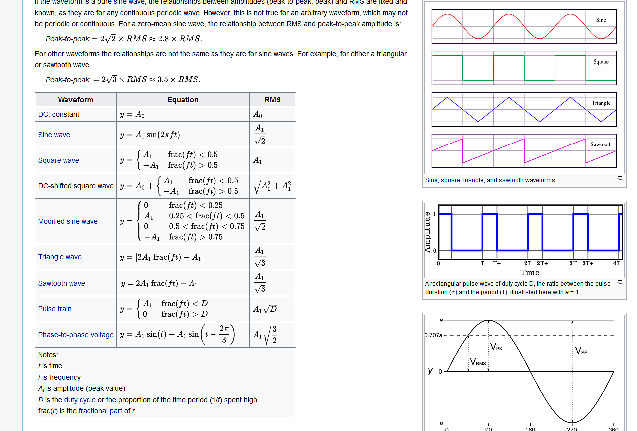
Pulse Vpk to Vrms, Vpk/√d at d=5% Vrms=0.22Vp
- but using Vpk/√2=0.707Vp thus result is 0.707/0.22= 3.2x true rms
- but using rectified Vavg, \$V_{RMS}=\frac{2}{\pi}V_{AVG}= 0.637 V_{AVG}\$
- then on the same pulse Vavg=Vpk*d=Vrms
- but if using the same conversion the error Vrms=0.637*Vavg
- your d=5% pulse error is -36.3% instead of +320%

enter image description here

This is just another approach and not necessarily the best which requires your error assumptions for power factor PF and crest factor (Pk/rms) with measurement error tolerance.

LPF method

Another approach is to apply a low pass filter on the rectified current waveform with -20dB at 4f. This steep filter is accomplished with an 8th order Butterworth LPF at 3f where f is the fundamental line frequency (50 or 60) This reduces the crest factor of noise pulses but can be implemented in one quad OpAmp with gain. and is 8x better than integration since it is 8th order with only 0.3% attenuation at f instead of -3dB (-31%). But then the same filter must be applied to voltage so that power factor angle difference does not change.

Best is a true RMS multiplier function or IC for RMS power.

\$\endgroup\$
16
  • \$\begingroup\$ Thank you very much for your input, but due to a lack of understanding everything you're saying, I will try what Barry is suggesting and if I'll fail with that, I will go with some specialized IC made for this application. In such case, is there some IC you would recommend? \$\endgroup\$
    – ProXicT
    Commented Apr 4, 2019 at 23:33
  • \$\begingroup\$ So as long as you can compute RMS over 1 or more cycles, that's better But you should still use some LPF e.g. -50dB at 1/2 the conversion rate ~1.65kHz otherwise you may get aliasing error \$\endgroup\$
    – D.A.S.
    Commented Apr 4, 2019 at 23:36
  • \$\begingroup\$ Do you understand the errors from not having a Nyquist filter? \$\endgroup\$
    – D.A.S.
    Commented Apr 5, 2019 at 0:06
  • 1
    \$\begingroup\$ You can use your audio channel as a scope, ya know how? \$\endgroup\$
    – D.A.S.
    Commented Apr 5, 2019 at 0:08
  • \$\begingroup\$ I hope I do, but I am still lost in how I would compute the attenuation of such low pass filter... You're saying -50dB at ~1.65kHz, that means I could use, for example, a 1k resistor with a 100nF capacitor, right? But how do I determine the attenuation? Just stop me if this is getting out of the boundaries of this question. \$\endgroup\$
    – ProXicT
    Commented Apr 5, 2019 at 0:09

Your Answer

By clicking “Post Your Answer”, you agree to our terms of service and acknowledge you have read our privacy policy.

Not the answer you're looking for? Browse other questions tagged or ask your own question.