3
\$\begingroup\$

Consider the Large and small signal model of the MOSFET amplifier,
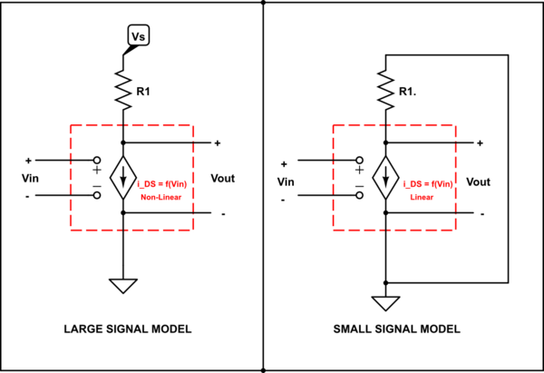
schematic

simulate this circuit – Schematic created using CircuitLab

How is this transformation valid, I get the linearization of the MOSFET, but then how can a source become a short and how can we reason the simplifications of other elements. I mean, the original circuit looks totally different from the small signal model. Please provide an intuitive answer, as I get the math part (i.e.) for small signal variations, the behavior of various elements are studied and then approximated, My question is how is this valid? For example, the small signal model of a resistor is simply the resistor itself because the resistor produces a corresponding voltage drop during the small wiggle that we supply, similarly wouldn't the Voltage source be unaltered during the 'wiggle', so shouldn't the small signal model of the Voltage source be itself ? Is there a non-mathematical explanation for shorting voltage source during small signal analysis?

\$\endgroup\$
4
  • \$\begingroup\$ We assume ZERO impedance between VDD (or Vs) and Ground. Hence the need for bypass capacitors. \$\endgroup\$ Commented Apr 8, 2019 at 4:23
  • \$\begingroup\$ Have you learned the Taylor series in math yet? \$\endgroup\$
    – The Photon
    Commented Apr 8, 2019 at 5:06
  • \$\begingroup\$ Yeah, I did. but then, is there a non-mathematical explanation for shorting voltage source during small signal analysis? \$\endgroup\$ Commented Apr 8, 2019 at 5:07
  • \$\begingroup\$ I think I can answer that question without referring to the Taylor series, but the more general question in your title ("Why does the small signal analysis work?") basically comes down to the Taylor series. \$\endgroup\$
    – The Photon
    Commented Apr 8, 2019 at 5:12

3 Answers 3

3
\$\begingroup\$

In small signal-analysis, the behavior of a non-linear device is approximated as linear about a DC operating point (Quiescent point). Basically we put in a small 'wiggle' signal that doesn't change things to much from the DC level. With a linear model we can apply the principle of superposition.

That is, the total response of the system can be viewed as the sum of the responses to each source individually. In your left picture there are two sources, a signal input from the left, and what is usually a DC power supply at the top. In the right hand picture, this source is simply being zeroed so the response to the input signal can be more easily determined. Therefore it is replaced by a short circuit to ground.

The actual behavior of the circuit is then this response, plus the response to the DC source alone.

\$\endgroup\$
4
  • \$\begingroup\$ So, do you say that the DC source is removed to apply superposition? Wait, the small signal model of a resistor is simply the resistor itself because the resistor produces a corresponding voltage drop during the small wiggle, similarly wouldn't the Voltage source be unaltered during the 'wiggle'? \$\endgroup\$ Commented Apr 8, 2019 at 4:35
  • \$\begingroup\$ @AravindhVasu, the small signal equivalent of a linear resistor is just the same resistor. But the small signal equivalent of a nonlinear resistor (for example, a PN-junction diode considered in the low-frequency limit) is a different resistor at every operating point. \$\endgroup\$
    – The Photon
    Commented Apr 8, 2019 at 5:05
  • \$\begingroup\$ Okay, is there a non-mathematical explanation for shorting voltage source during small signal analysis? \$\endgroup\$ Commented Apr 8, 2019 at 5:07
  • \$\begingroup\$ I get the fact that we are linearly approximating a device , but I just cant digest(reason) vanishing the source. \$\endgroup\$ Commented Apr 8, 2019 at 5:09
0
\$\begingroup\$

wouldn't the Voltage source be unaltered during the 'wiggle', so shouldn't the small signal model of the Voltage source be itself ?

When we talk about the small signal circuit, we are asking how much will the voltages and currents in the circuit change due to a small change in some input excitation (usually due to a voltage or current source).

If you change the input voltage to a circuit that contains an ideal voltage source, the voltage across that source doesn't change at all (that's why we call it ideal).

Since the voltage change is 0, its equivalent component in the small-signal circuit is a 0 V source.

The voltage assigned to the source (or any other component in the circuit) in a small-signal model is not its actual voltage, it's the voltage change due to the small-signal excitation.

\$\endgroup\$
4
  • \$\begingroup\$ But wouldn't shorting the DC voltage change the bias point and stuff? Please Bare with me here :) \$\endgroup\$ Commented Apr 8, 2019 at 5:14
  • \$\begingroup\$ You don't short the voltage in the DC model used to find the operating point, only in the small-signal model used to find the effects of small changes in the inputs. \$\endgroup\$
    – The Photon
    Commented Apr 8, 2019 at 5:14
  • 2
    \$\begingroup\$ Yeah okay, so to study small changes in the input, we form a separate linear circuit by substituting for each component its small signal component, which is the response that the specific component gives during the small wiggle, and the voltage source doesn't contribute anything to the change in output, so we short it ,am I right? \$\endgroup\$ Commented Apr 8, 2019 at 5:18
  • \$\begingroup\$ @AravindhVasu, yes, that's it. \$\endgroup\$
    – The Photon
    Commented Apr 8, 2019 at 5:19
0
\$\begingroup\$

I'd like to add one more bit of intuition to the already existing and accepted answers: negative feedback.

The reason why small-signal analysis is also used is because we, normally, use those circuits within a feedback a loop. Therefore, they aren't really amplifying the full-swing of your input voltage signal (in case of a voltage-voltage or voltage-current amplifier), but only the error signal.

As we know, the error signal(*) is very small if we have a large loop gain. Therefore, the error signal pretty much becomes the small signal in our "small-signal analysis" and thus, we can make very accurate predictions about how the feedback amplifier will behave.

It'd make zero sense to do small-signal analysis and use it as an open-loop because there is a high chance that the signals they're driven with are not small at al, thus their DC properties can change with the signal swing. Harold Black (inventor of electronic feedback amplifiers) suffered from this exact problem at work before he got his inspirational flash of the feedback amplifier in the ferry to work.

*When we analyze an op-amp, assuming that V+ = V- (the input ports of the op-amp) is equivalent to assume that the error signal equals zero, i.e. infinite loop gain.

\$\endgroup\$

Your Answer

By clicking “Post Your Answer”, you agree to our terms of service and acknowledge you have read our privacy policy.

Not the answer you're looking for? Browse other questions tagged or ask your own question.