1
\$\begingroup\$

In the T-equivalent circuit model of a MOSFET in small signal analysis the MOSFET shows an infinite resistance between its gate and source when looking from the gate while it shows very little resistance when looking from the source.

I can't see how it can shows two different resistances like that. If the current has no path from the gate to source how it can be that it has a path from the source to gate - it's completely isolated by the SiO2 layer

One more thing is that in first glance I thought that since it's a small signal analysis the capacitive gate should be represented as a short circuit like we do with normal capacitors in the small signal analysis but instead the analysis seems to assume an open circuit in the common source configuration and a short circuit in the common gate one.

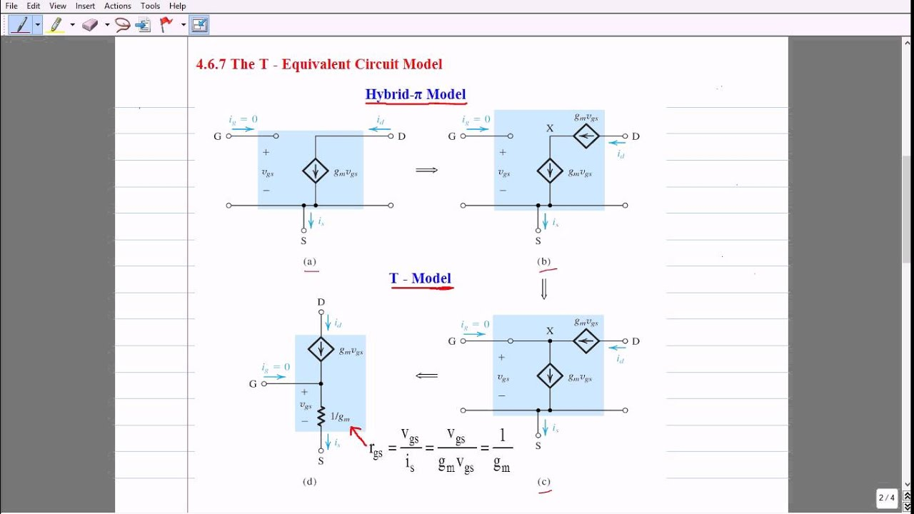
enter image description here

\$\endgroup\$
2
  • 1
    \$\begingroup\$ In the small-signal analysis, we shorting only external capacitors, which will form high pass filters. Thus for signal frequency, Xc is very small (Xc ≈ 0Ω). But internal parasitic capacitors we do not treat as a short-circuit. If we interested in "high-frequency" response we can add them to the circuit \$\endgroup\$
    – G36
    Commented Dec 10, 2020 at 17:09
  • 1
    \$\begingroup\$ I edited the title to present the problem. Cancel the edit if it's wrong. \$\endgroup\$
    – user136077
    Commented Dec 11, 2020 at 15:10

4 Answers 4

3
\$\begingroup\$

Mahmut S....the 1/gm "resistance" is - in fact - not a real resistor. In no case it is a quantity which exist in a real fet and could be found between G and S. It's a pure mathematical trick to make the model to obey the same equations as the other models.

In small signal AC analyses T-model works as well as the other shown models, but having a resistor between G and S is confusing and makes difficult to see the basic idea of gm - the control function between Vgs and Id. As a teacher of engineering students I do not like it, no matter it's mathematically right.

My recommendation: Don't use the T-model. Use the equivalent models with gm as a voltage-controlled current source.

\$\endgroup\$
7
  • \$\begingroup\$ user287001...The transconductance is gm=d(Id)/d(Vgs), correct? So it relates the current between D and S and the voltage between two other nodes (G and S). Hence, it cannot fulfill Ohms law. I did not say that the T-model would not work. My only concern is that it can confuse some people (as we have seen !!). Do you see any necessity to use such a confusing model - if compared with the other model that clearly shows what will happen: Id=f(Vgs) with the transconductance gm as a controlling quantity . \$\endgroup\$
    – LvW
    Commented Dec 10, 2020 at 15:42
  • \$\begingroup\$ I wonder if the person who has decided to downvote again this contribution is fair enough to tell us why? \$\endgroup\$
    – LvW
    Commented Dec 10, 2020 at 16:38
  • \$\begingroup\$ OK - I agree partly. I admit that within the small-signal equivalent ac diagram the part 1/gm acts as a dynamic resistance and, hence, can obey Ohms law. Nevertheless, my primary concern is a good "understanding" of the physics behind all the formulas. And - from my experiences with many students - I have learned that this part re=1/gm=d(Vgs)/d(Id) causes some misunderstandings when its role is applied to the real transistor where it does NOT act as a two-port device (resistor). The situation is even more confusing because some authors are using the term "intrinsic emitter resistance". \$\endgroup\$
    – LvW
    Commented Dec 11, 2020 at 8:29
  • \$\begingroup\$ To make my position clear: From the physical point of view, the quantity gm is a transconductance and 1/gm=re is a transresistance (hence, it is no resistor which can obey Ohms law). However, when this quantity re=1/gm is used as an element within an equivalent ac small signal diagram (T-model) it can be treated during all the calculations as a resistive element following Ohms law. I think you can agree to this, right? \$\endgroup\$
    – LvW
    Commented Dec 11, 2020 at 8:38
  • \$\begingroup\$ OK - agreed. Thank you. \$\endgroup\$
    – LvW
    Commented Dec 11, 2020 at 11:37
1
\$\begingroup\$

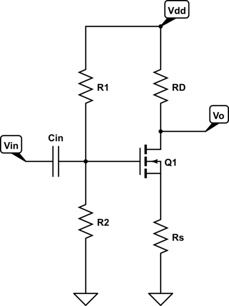
Let us try to analyze the CS amplifier using T-model.

schematic

simulate this circuit – Schematic created using CircuitLab

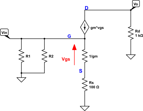
And the small-signal representation:

schematic

simulate this circuit

As you can see we have (KVL in action):

$$v_{in} = v_{gs} + i_sR_S = i_s\frac{1}{g_m} + i_s R_S = i_s(\frac{1}{g_m} + R_S)$$

And

$$v_o = -i_dR_D$$

And because \$i_d = i_s\$ we have a voltage gain equal to:

$$\frac{v_o}{v_{in}} = \frac{-i_d R_D}{i_s(\frac{1}{g_m} + R_S)}=$$

$$ = - \frac{R_D}{\frac{1}{g_m} + R_S}$$

Now let us try to find \$i_d\$ current

$$i_d = g_mv_{gs}$$

Additional

$$v_{gs} = v_{in}\frac{\frac{1}{g_m}}{R_S + \frac{1}{g_m}} $$

Thus, the drain current is:

$$i_d = g_mv_{gs} = g_m v_{in}\frac{\frac{1}{g_m}}{R_S + \frac{1}{g_m}} = \frac{v_{in}}{R_s +\frac{1}{g_m}} $$

And now notice that the source current is:

$$i_s = \frac{v_{in}}{\frac{1}{g_m} + Rs} $$

Thus, we see that the gate current is 0A.

$$i_g = i_d - i_s =\frac{v_{in}}{R_s +\frac{1}{g_m}} - \frac{v_{in}}{\frac{1}{g_m} + Rs} = 0A $$

As you can see no gate current is flowing into the "gate" in T-model.

\$\endgroup\$
2
  • \$\begingroup\$ Yes - agreed. Good derivation. This result (ig=0) can also be visualized directly from the T-model - if interpreted correctly!. Of course, this diagram (T-model) gives the same results as the classical Pi-model. But my question still exists: Where are the advantages of this T-model if compared with the Pi-model? We all know that the FET is a voltage-controlled current source - and THIS fact is clearly represented in the PI-model. In contrast, the T-model shows a resistive symbol (1/gm), which is - from the physical point of view - NOT a resistor. So - why should we use this T-model? \$\endgroup\$
    – LvW
    Commented Dec 10, 2020 at 17:25
  • \$\begingroup\$ For sure we can live without T-model and always uses the PI-model. But I think that the T-model was created to analyze the common gate stage. Because now, we directly see that rin = 1/gm. \$\endgroup\$
    – G36
    Commented Dec 10, 2020 at 17:43
1
\$\begingroup\$

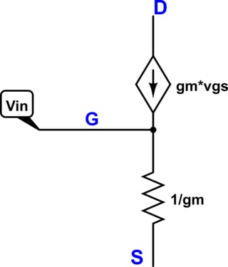
I think you're misunderstanding the models. Let's look at the T model:

schematic

simulate this circuit – Schematic created using CircuitLab

The current flowing into the drain is \$g_mv_{gs}\$. The current flowing out of the source is \$v_{gs}/r_{gs} = v_{gs}/\frac{1} {g_m} = g_mv_{gs}\$. Since the drain and source currents are always equal, there is no gate current. I think the T model is drawn this way because in a BJT, \$r_{gs}\$ is \$\frac \alpha {g_m}\$, which does allow for some base current. In the hybrid-pi model, \$r_\pi\$ becomes 0 for a MOSFET, so the resistor is removed from the schematic entirely.

There is no difference between the gate-source "resistance" and the source-gate "resistance". There's no diode or anything. In this model, there's no gate current.

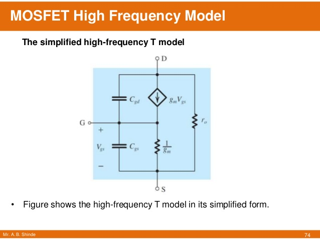
This version of the model does treat the gate capacitance as an open circuit. For high-frequency analysis, you have to include the capacitance between the terminals -- \$C_{gd}\$, \$C_{gs}\$, and \$C_{ds}\$. (Although \$C_{ds}\$ is small and can often be ignored.) Here's what that looks like (source is slide 74 from here):

High-frequency T model

There's still no low-frequency gate current.

\$\endgroup\$
2
  • \$\begingroup\$ Could you please provide a link or citation for the second graphic that you copied into your answer? We want to be sure to give credit to the original creator. \$\endgroup\$ Commented Dec 10, 2020 at 21:10
  • \$\begingroup\$ @ElliotAlderson Done. \$\endgroup\$
    – Adam Haun
    Commented Dec 11, 2020 at 0:09
0
\$\begingroup\$

Models which try to describe how the AC components of the voltages and currents are related with each other are not images of physical structures. Your problematic T-small signal model works approximately like a fet when only weak enough AC components are taken into the account.

Ig=0 because the voltage dependent current source makes just enough current to compensate the current that the resistor would sink from the gate in case the current source was removed. The apparent G-S resistance seen from the gate becomes infinite, no matter there's a finite resistor.

Small signal models assume certain proper DC operating point (=idle DC components of the voltages and currents) which are left out in small signal AC analysis. The trick to get those DC components right is called "biasing".

\$\endgroup\$
6
  • \$\begingroup\$ I don't get how this explain the two different resistance values in both cases \$\endgroup\$ Commented Dec 10, 2020 at 12:21
  • \$\begingroup\$ It doesn't matter if the Resistor value is too high or infinite it's just confusing to me that there's a very high resistance value in one configuration and very small one in the other clearly no matter what the gate current will be very small \$\endgroup\$ Commented Dec 10, 2020 at 12:25
  • \$\begingroup\$ Can you possibly see how two 10 Ohm resistors in parallel with no other parts produce total 5 Ohm resistance? There's also 2 different values, no matter there's only 10 Ohm resistors. The equivalent resistance 5 Ohm can be calculated with circuit analysis. A calculation of the equivalent resistance between G and S will produce infinite (=zero total conductance). \$\endgroup\$
    – user136077
    Commented Dec 10, 2020 at 12:28
  • \$\begingroup\$ Yes but it's a capacitive gate so Shouldn't it be a short in the analysis? if not How the resistance is very small when looking from the source if there will be no path (ideally) between the gate and the source as assumed in the first case it just doesn't make sense to me \$\endgroup\$ Commented Dec 10, 2020 at 13:37
  • 1
    \$\begingroup\$ Listen, buddy! These models are idealized. They assume all capacitances=zero inside the fet. Zero capacitance between 2 points means no connection between those points caused by capacitors. These models are different simple circuits which all satisfy equations Id=(Vgs)*(gm). AND Ig=0. These models do not claim to present the structure of a real fet except the fact that there are three wires named D,G and S. \$\endgroup\$
    – user136077
    Commented Dec 10, 2020 at 19:24

Your Answer

By clicking “Post Your Answer”, you agree to our terms of service and acknowledge you have read our privacy policy.

Not the answer you're looking for? Browse other questions tagged or ask your own question.