What is the proper way to measure 0-240v 50-60hz Mains AC with an arduino / 3.3v mcu?
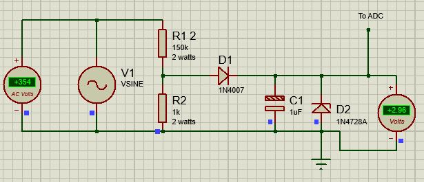
(Edited to include a diagram of a proof on concept, which is transformerless)
Can anyone confirm that this is the right choice, or provide reasons why this wouldn't work as I intend, given the requirements mentioned below? Keep in mind, I plan to use this in a commercial product
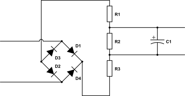
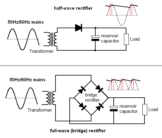
I've been researching the webs through so many ways to accomplish this, from octocouplers, mid400, LM2902N, tl081, voltage dividers, transformers, etc.. for a production product I have in mind, but I haven't ended up an any clear solutions. I'm hoping to get a clear sense of direction.
I'll leave this at the basics and provide more info needed.
I found these seemingly simple devices on amazon, same concept, being plugged into a general US home outlet, but I want to accomplish it using an Arduino. (I.E. I want to read the output via serial.)
- https://www.amazon.com/dp/B00PBW5A4I/
- https://www.amazon.com/Yeeco-Display-Digital-Voltmeter-Voltage/dp/B00PZBEJ7Y/
Requirements:
- Read value of 0-240v (or higher) from AC Mains 0-240v 50-60hz to analog input of 0-3.3v for a microcontroller. (+/- 1% tolerance is probably acceptable aside from 0)
- Safety from reverse polarity/shorts
- Safety from voltage spikes
- Smallest form factor possible. Unit is handheld & battery powered, so prob not enough room for transformers.
- Low heat dissipation (all parts are enclosed in small handheld unit)
Not worried about:
- Isolation to user (device is presumed to be live)
- Powering the device from mains (mcu is powered by battery)


