0
\$\begingroup\$

What is the proper way to measure 0-240v 50-60hz Mains AC with an arduino / 3.3v mcu?

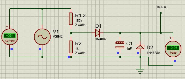
(Edited to include a diagram of a proof on concept, which is transformerless)

enter image description here

Can anyone confirm that this is the right choice, or provide reasons why this wouldn't work as I intend, given the requirements mentioned below? Keep in mind, I plan to use this in a commercial product

I've been researching the webs through so many ways to accomplish this, from octocouplers, mid400, LM2902N, tl081, voltage dividers, transformers, etc.. for a production product I have in mind, but I haven't ended up an any clear solutions. I'm hoping to get a clear sense of direction.

I'll leave this at the basics and provide more info needed.

I found these seemingly simple devices on amazon, same concept, being plugged into a general US home outlet, but I want to accomplish it using an Arduino. (I.E. I want to read the output via serial.)

Requirements:

  • Read value of 0-240v (or higher) from AC Mains 0-240v 50-60hz to analog input of 0-3.3v for a microcontroller. (+/- 1% tolerance is probably acceptable aside from 0)
  • Safety from reverse polarity/shorts
  • Safety from voltage spikes
  • Smallest form factor possible. Unit is handheld & battery powered, so prob not enough room for transformers.
  • Low heat dissipation (all parts are enclosed in small handheld unit)

Not worried about:

  • Isolation to user (device is presumed to be live)
  • Powering the device from mains (mcu is powered by battery)
\$\endgroup\$
5
  • \$\begingroup\$ Thanks for catching that @SamGibson. I meant to change the title to 240v as well. There was no specific reason to want 600v other than seeing other similar devices claiming to support that voltage. Rather than limit my options, I decided to go back down to most typical use-case levels seen on general Mains receptacles. \$\endgroup\$
    – cEMa
    Commented Apr 16, 2019 at 4:25
  • 2
    \$\begingroup\$ "Device is presumed to be live." So is the programming port and if you connect it to a PC / laptop USB port while mains is connected you will probably destroy both. \$\endgroup\$
    – Transistor
    Commented Apr 16, 2019 at 6:09
  • \$\begingroup\$ Thanks for the comment @Transistor. The end user would not be in direct contact with the internals, they would have to deliberately open the device, plug it in a live mains, and touch the actual circuit/prongs I included. Please elaborate the real-world consumer risk to the end-user and/or provide some insight as to how you would mitigate the risk. \$\endgroup\$
    – cEMa
    Commented Apr 16, 2019 at 14:35
  • \$\begingroup\$ Use a small isolating transformer. \$\endgroup\$
    – Transistor
    Commented Apr 16, 2019 at 16:22
  • 1
    \$\begingroup\$ @Transistor Thanks for the follow up. I'm genuinely interested and want to take legitimate safety concerns into the circuit. However a transformer seems unnecessary given the end-use case as a finished product. Please elaborate on the real-world consumer risk to the end-user, if the end user would not be in contact with the internals. They would have to deliberately break/open the device, plug it into live mains, and touch the actual circuit/prongs. \$\endgroup\$
    – cEMa
    Commented Apr 16, 2019 at 18:56

2 Answers 2

2
\$\begingroup\$

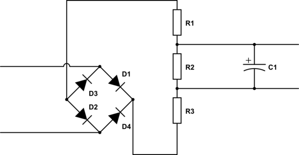
schematic

simulate this circuit – Schematic created using CircuitLab

Try to combine both solutions - bridge rectifier and RC-filter combined with voltage divider.

Although your device is handheld and powered from internal battery using triple resistor divider will no cause 'common ground wire' problem. Only errors of measurement.

Because you are talking about meassuring of AC Voltage - there will no be 'reverse polarity' problem.

\$\endgroup\$
3
  • \$\begingroup\$ Thanks @Alexander for the reply! For the basic purpose of measuring voltage, what benefits does your circuit have over my own? Seems like a waste of money to have 3x the components and arrive at same result. In my head I'm thinking it's just allowing me to use lesser rated resistors and give an even more condensed wave form. \$\endgroup\$
    – cEMa
    Commented Apr 16, 2019 at 14:22
  • \$\begingroup\$ 1. No common ground (blue dots) 2. Smaller capacitance of capacitor and more smooth voltage line - better accuracy of measurement. \$\endgroup\$
    – Alexander
    Commented Apr 16, 2019 at 14:28
  • \$\begingroup\$ Because you are talking of measuring AC voltage there will exist at least one diode and one capacitor. Minimum 2 resistors for divider or transformer. \$\endgroup\$
    – Alexander
    Commented Apr 16, 2019 at 14:30
0
\$\begingroup\$

At these high voltages, I don't think that you will find many "off-the-shelf" options for voltage measurement via Arduino or a similar ecosystem at the usual suspects (Sparkfun & Adafruit). However, you can fairly easily assemble your own circuit for this with a small number of components.

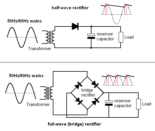
Here's an example from DIY-Audio-Heaven (https://diyaudioheaven.wordpress.com/tutorials/power-supplies/rectifiers/)

enter image description here

Breaking down what the circuit does:

  1. First, a measurement transformer is needed to reduce you (very high) AC voltages to something lower that the Arduino or other MCU can deal with. You will need to do your own search to find a transformer with a turns ratio and isolation voltage that meets your requirements (for example a 100:1 turns ratio transformer would reduce your 600 VAC to 6 VAC). Transformers above 600 VAC are tricky to find based on a quick search.
  2. Second, a full-wave bridge rectifier circuit implemented with diodes (these can be purchased a standalone 'bridge rectifier' components depending on your sizing requirements) converts the AC full-wave into a positive voltage half-wave
  3. A large reservoir filtering capacitor is used to 'smooth' out AC half wave to a 'DC' voltage (approximately, there is still some fluctuation dependent upon the capacitance used). A capacitor value of 100 uF seems pretty common. This signal could be additionally filtered, scaled by a voltage divider to a different DC voltage of interest, etc. In your case, if below 5VDC, it can be measured directly by the Arduino UNO or similar ADC (analog-to-digital converter).

Further reading - I heavily referenced this post in writing this answer: https://www.electronics-tutorials.ws/diode/diode_6.html

\$\endgroup\$
1
  • \$\begingroup\$ Thanks for taking to time to respond @Liquid Plasmas, I really appreciate it. I don't think a transformer solution will be possible due to the lack of space in the device, the additional weight is also a downside. See my updated question and diagram to see if it sparks any further thoughts/ideas/solutions/fright. Thanks again! \$\endgroup\$
    – cEMa
    Commented Apr 16, 2019 at 6:17

Your Answer

By clicking “Post Your Answer”, you agree to our terms of service and acknowledge you have read our privacy policy.

Not the answer you're looking for? Browse other questions tagged or ask your own question.