0
\$\begingroup\$

I'm looking for a way to limit the speed of some wheelchair motors in order to gain better control when using them in my RC device.

Currently the motors are very sharp and don't ramp up to speed, which makes it difficult to make delicate movements.

As such I thought that reducing the input voltage would help; but I wanted to do this in a way that I could adjust the amount of speed limiting. E.g. 12V slow speed - 24V max speed (and anywhere in between).

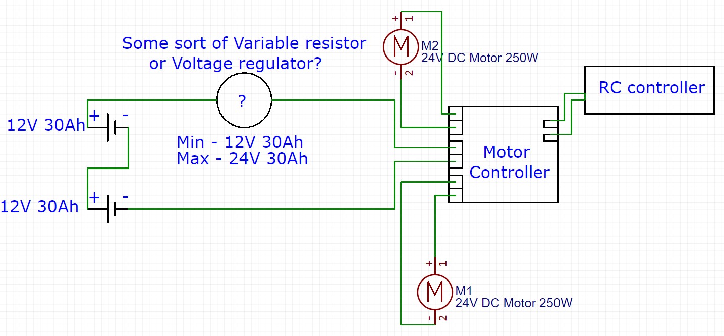
As such, I thought some sort of Voltage Regulator/Variable resistor would be appropriate, but I'm concerned when it comes to the Amperage value and need a bit of guidance - or to be honest - told if this is the correct way of thinking or not.

I've sort of drawn out a (very basic) sketch of the proposed wiring diagram for your consideration.

enter image description here

Any help with this would be much appreciated.

Thanks


[Update]

Thanks for all the replies - I thought it best to update the post.

The motor controller I'm using is from a Company called Cytron: Cytron 30A Bi-directional Dual Channel DC Motor Driver Controller. Link: enter link description here. enter image description here
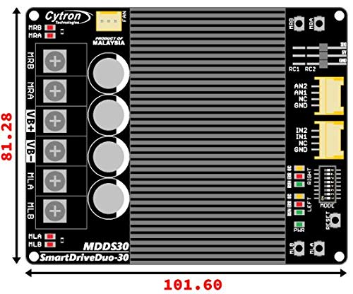
Whilst I do have full control over the speed of the device, it's the granularity and sharpness I'm looking to smooth out - as well as add a variable speed limiter that allows me to select a maximum speed so that if I were to loose concentration and pushed the joystick to top speed, it would max out at 3Mph for an indoor environment or full speed outside.

\$\endgroup\$
5
  • \$\begingroup\$ Speed control should be a function of your motor controller. If it is not giving you good controllability through the desired speed range, you may need to seek a better one, recalibrate the endpoints, or improve the firmware. What you desire is a key component of any decent large scale RC or robot-wars type ESC. \$\endgroup\$ Commented Apr 17, 2019 at 0:12
  • \$\begingroup\$ Another option would be to change the mechanical ratio coupling to the wheels - something more easily done if you have say toothed drive belts. Or even changing the size of the (driving) wheels. \$\endgroup\$ Commented Apr 17, 2019 at 0:15
  • \$\begingroup\$ No power MOSFETS to implement PWM? \$\endgroup\$ Commented Apr 17, 2019 at 0:15
  • \$\begingroup\$ Wheelchairs usually have delicate speed control or did you only take the motor? \$\endgroup\$
    – Solar Mike
    Commented Apr 17, 2019 at 4:10
  • \$\begingroup\$ I've just added an update to the main topic body. Thank you for your help so far. So I do have full control of the speed of the motors, but want to add a variable limiter in order to reduce the speed of the device for different uses, Indoor and outdoor, essentially as a safety measure and to allow for smoother control. I have just used the Motors from the wheelchair. I have the controller box, but chose to remove it from the loop for ease. \$\endgroup\$ Commented Apr 17, 2019 at 14:51

3 Answers 3

0
\$\begingroup\$

OK so if I understand correctly, you're trying to do 2 things:

1) Smooth the motor driver output so it's not jerky if you push your joystick to 100% fast

2) Add an extra feature where the max speed is different indoors and outdoors

1 can maybe be resolved by getting a different driver that does this smoothing, but it might be hard to find. 2 requires that you add custom hardware or a microcontroller. If you're not particularly comfortable designing electronics, the easiest way to go about this might be to add a microcontroller between the RC controller and the motor controller, and write code that implements the smoothing and the indoor/outdoor feature. You can connect the RC1 and RC2 signals to ADC pins, and control the motor controller via serial, PWM, or DACs (see manual). Connect whatever you're using to detect if you're indoor or outdoor to the microcontroller as well. Adafruit's Trinket Pro 5V would do if you use serial - https://www.adafruit.com/product/2000 . If you're comfortable with Arduino, this should be pretty straight forward. Good luck!

\$\endgroup\$
4
  • \$\begingroup\$ Interesting. Perhaps I will forego the Smoothing for now. 2: So this would be replacing the Current R/C receiver with a Micro-controller (Arduino) and connecting that to the R/C controller. As a 'detector' I wouldn't need a sensor or anything like that - I don't need it to be that smart, I'd be happy with a manual selector switch (Indoor - slow speed /or/ Outdoor - Max speed), would that be possible using this method? \$\endgroup\$ Commented Apr 18, 2019 at 14:53
  • \$\begingroup\$ That's right. If you're happy with a switch for toggling indoor/outdoor mode, then just use that connected to the microcontroller (with a pull-up resistor). You can also do all the speed smoothing in the microcontroller: if you read a sharp speed increase coming from the RC receiver, you output a smooth speed increase for the motor controller. The motor controller never sees the sharp change in speed. \$\endgroup\$ Commented Apr 18, 2019 at 17:17
  • \$\begingroup\$ Great! I will have to brush up my coding skills. In theory I would also be able to add a remote 'kill switch' using this method as well right? (Basically something that would just cut the power to the motors) \$\endgroup\$ Commented Apr 24, 2019 at 17:06
  • \$\begingroup\$ Yep, absolutely \$\endgroup\$ Commented Apr 24, 2019 at 17:11
0
\$\begingroup\$

If you have the ability to use pulse-width modulation (PWM), that's generally the way to go in my opinion. Adding resistors will create a lot of heat and waste battery energy. You can create a smoother ramp-up via SW my ramping up the PWM duty cycle from 0% to 100% over a few seconds.

\$\endgroup\$
3
  • \$\begingroup\$ PWM is indeed the solution, but the system already appears to contain a PWM controller, so the issue is likely that it is not suitable or not suitably tuned for the need. \$\endgroup\$ Commented Apr 17, 2019 at 0:13
  • \$\begingroup\$ I agree. I guess the missing piece of info here is whether the controller has an adjustable control input that's not being used or whether the controller is ON-OFF control only by design and therefore not suitable as you are proposing. \$\endgroup\$ Commented Apr 17, 2019 at 0:29
  • \$\begingroup\$ Thanks for your help so far - I've added an update to the main body. From my understanding of the board, I don't think it is using PWM as PWM would be used when using a micro Controller such as an Arduino... but I could be (and probably am) wrong in that belief. I believe it to be an On/Off design - which is why I thought the only way to limit the speed would be to reduce the input Voltage to the motors. \$\endgroup\$ Commented Apr 17, 2019 at 14:59
0
\$\begingroup\$

If I'm reading this correctly, you're already aware of H bridges and motor controllers and all that?

So then what you're looking for is some sort of low gear / high gear sort of deal to make the system more controllable in small spaces and still fast enough for outdoors?

Here's some options I would consider:

  1. Get a better motor controller. There's no electrical reason that a controller can't go very slow with a full voltage. Combine that with a dual rate switch on the RC side.

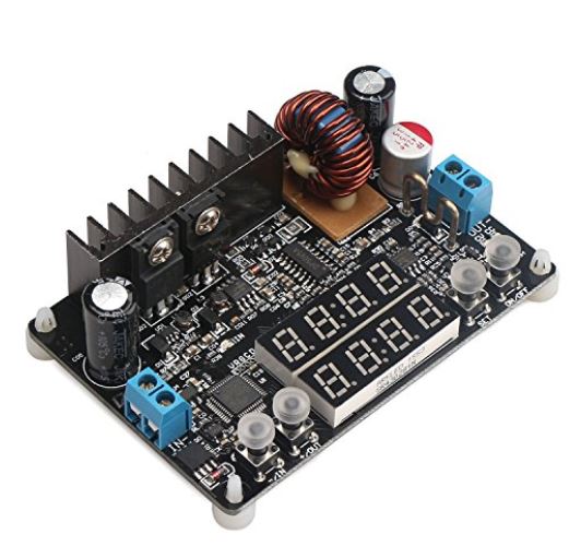
  2. Maybe that's not an option for some reason? In that case you could try to use a high power DC switching regulator. You could either try to control the regulator output, or just hook up some relays to use or bypass the regulator. The trouble will be finding a regulator that can supply enough power. These types available on amazon are fairly economical if your current is less than say.. 10A: DC Buck Converter, DROK DC-DC Step Down Voltage Regulator 10V-75V 60v 24v to 0-60V 12v 5v 12A DKP6012 Digital Control Volt Reducer Board Power Supply Module with LED Display & CC CV Mode

enter image description here

\$\endgroup\$
2
  • 1
    \$\begingroup\$ That regulator isn't going to handle this job. There's a reason people don't use switching regulators for this and it is a) they are unnecessary and b) they are hard to build powerful enough. The solution is not to add a regulator while using the wrong PWM speed controller, but rather to use the right PWM speed controller. \$\endgroup\$ Commented Apr 17, 2019 at 2:37
  • \$\begingroup\$ Yes, I agree. That was literally the first thing I suggested. However in the real world, hacks are sometimes necessary. \$\endgroup\$
    – Drew
    Commented Apr 25, 2019 at 20:11

Your Answer

By clicking “Post Your Answer”, you agree to our terms of service and acknowledge you have read our privacy policy.

Not the answer you're looking for? Browse other questions tagged or ask your own question.