1
\$\begingroup\$

I know that 4 - wires method uses 2 wires for driving current throught ammeter and measure current values. So, resistivity wires will be removed from the equation. Ammeter wires resistance has no effect on current measure because wires resistance and ammeter are also serially connected with the source supply.

Voltage on Subject Resistance is measured by a parallel connected voltmeter (2 wires more). As it has a big intern resistance it has no significant current passing through this device. So, voltimeter resistance wire will has no effect to the voltage measure, but potential contact with Subject Resistance terminals. These two potential appearing in contact vA and contact vB will be cancelled when source supply polarity changes and two values of ammeter and voltage will be took and added in a expression like this:

  1. V+ = vA + I·R -vB
  2. V- = -vA + I-·R +vB
  3. V- + V+ = (I- + I+)·R --> vA and vB has been cancelled because they are signed opposed

By the way that explanations I' ve found it seems to say that wire length doesn' t matter. But I' m almost sure that length and connector position does.

But the fact is that I don' t find explanations where to see whether this principle is only true when:

  • voltmeter and wires amperemeter have the same distance respect Resistance Subject. Does it works correctly if 4 wires have different length?

  • must the ammeter and voltmeter two both contacts be connected at the same place? Does it works if ammeter connector has a distance between ammeter connectors and voltmeter connectors?

  • Could there be some distance between the connectors and Subject Resistance terminals? or must they be connected close to Subject Resistance terminals?

Could anyone clarify when the 4 wires method will totally cancel contacts potential and wire resistance in these three prior indicated situation?

Some images as example of distances, wires and connector position possibilities:

enter image description here

If I need to extend subject R terminals by signle wire I will get this circuit with 2 new resistances -R10 and R9- at the ammeter net shared with voltmeter one too:

enter image description here

So they R9 and R10 will experiment a potential because of the current passing through the left net. So I think that being connector the more closer to the subject R terminals is a condition. If not, make me know.

\$\endgroup\$
9
  • \$\begingroup\$ I've always understood the Kelvin Connection to be used with 4 wires connected to a load: 2 wires to drive current and 2 wires to sense voltage. \$\endgroup\$ Commented May 29, 2019 at 10:02
  • \$\begingroup\$ Where is your load in the diagrams? \$\endgroup\$
    – Andy aka
    Commented May 29, 2019 at 10:03
  • 1
    \$\begingroup\$ I think you're overthinking and maybe misunderstanding the 4 wire / Kelvin measurement method. Please read: allaboutcircuits.com/textbook/direct-current/chpt-8/… The goal is to eliminate the influence of wire resistance. You mention length: length by itself is irrelevant, it is the resistance that's relevant. If there's current flowing through such a wire resistance, a voltage develops across it. The 4-wire method measures in such a way that this voltage drop does not influence the measurement. \$\endgroup\$ Commented May 29, 2019 at 10:03
  • \$\begingroup\$ @Andyaka at Rs Resistance \$\endgroup\$
    – Suvi_Eu
    Commented May 29, 2019 at 12:11
  • 1
    \$\begingroup\$ I think the trick consists in put voltmeter and ammeter contacts just close to the subject resistance For the Voltmeter: yes, that is essential. For the Current meter: no, it does not matter! You can use very long wires and put the current meter anywhere you like as long as the current through the resistor also flows through the Current meter. \$\endgroup\$ Commented May 29, 2019 at 13:48

3 Answers 3

2
\$\begingroup\$

schematic

simulate this circuit – Schematic created using CircuitLab

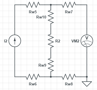
Consider the two circuits above, we want to measure R1 and R2.

Assume Rw1 to Rw8 represent the wiring resistances.

We know \$ R = \dfrac{V}{I}\$ and all wires have resistance. Assume volt meters are perfect (taking no current) and that the current supplies have internal current meters.

The circuit on the left represents a two wire measurement the current flowing out of R1 causes voltage drops across all three components due to the resistance of the wire. I1 sees the largest voltage, then VM1 then R1. This measurement of R1 is an overestimate because of these drops.

In the circuit on the right we have a 4 wire 'kelvin' connection current flows out of I2 and through R2 so there is slightly more volts across I2 than R2 but we don't care. VM2 is accurately measuring the voltage across R2 because there is no current flowing in that loop so we measure R2 correctly.


In principle these wires could be any length with two obvious limitations

  • Very long wires from the current source may prevent it from the current required. The current source usually has a low maximum voltage.

  • The wires to the voltmeter have a high impedance load at one end so may pick up additional signals in an electrically noisy environment. This may be mitigated by using a twisted pair.

I have never seen a problem with cables of the sort of length you typically find in a test lab however.

\$\endgroup\$
2
  • \$\begingroup\$ Thanks @Warren Hill, I know this. But my question is if-thanks to this 4 wire principle- length doesn' t affect to the accuracy of the mesaure. Could the ammeter wires have 5· length of voltmeter wires length (ammeter wires L = 5· volmeter wires L) and having the same measure than having ammeter wires L = 5· volmeter wires L? In an article that I have read it is implied that Voltmeter and Ammeter they both must be at the same distance from Subject R. But I'm not sure. So, the question is, could wires be any distance to the Subject R and the measure will get the same value for any wires length? \$\endgroup\$
    – Suvi_Eu
    Commented May 29, 2019 at 12:38
  • 1
    \$\begingroup\$ I have done this with ammeter cables over 2m and 50mm voltage cables without seeing any problem. I got the same result when I tried this the other way round. In practice no but I have extended my answer to consider theoretical answers with very long cables. \$\endgroup\$ Commented May 29, 2019 at 13:33
1
\$\begingroup\$

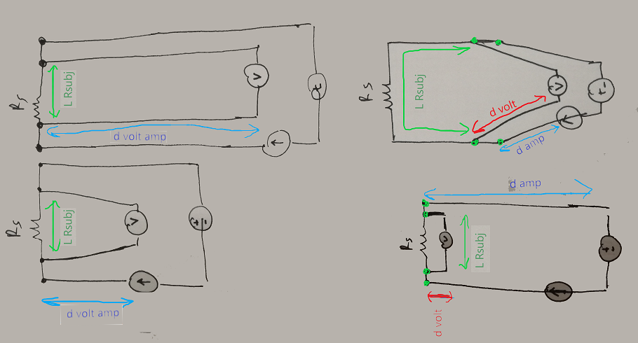
Consider a loop of current flowing between a current source and a resistor under test. The distance between the nodes at which you connect the voltmeter to that current loop defines the size of the resistor under test.

The lengths of the voltmeter and ammeter wires going to those nodes do not matter. If the resistor includes any wire between itself and those nodes, it will be measured as part of the defined resistor.

enter image description here

In the lefthand diagram above, you measure the resistance of Rs, and any wires that connect Rs to the voltmeter connection nodes, the path marked by the L_Rsubj in green. This is probably what you want.

In the righthand diagram above, you measure the resistance of Rs, and any wires that connect Rs to the voltmeter connection nodes, the path marked by the L_Rsubj in green. This is probably what you want.

In the lefthand diagram below, you measure the resistance of Rs, and any wires that connect Rs to the voltmeter connection nodes, the path marked by the L_Rsubj in green. This is probably what you want.

In the righthand diagram below, you measure the resistance of Rs, and any wires that connect Rs to the voltmeter connection nodes, the path marked by the L_Rsubj in green. This is probably not what you want.

The measurement includes the resistance of the long wires on either end of Rs. Although you are making a 4-wire measurement of 'Rs plus its wires', you are making a conventional '2 wire' measurement of Rs alone. You only have two wires going to it, so these wires have a V=IR drop in them due to the excitation current, and the voltmeter is measuring that drop in addition to the IR drop across Rs . As your total voltage drop includes the drop on those wires, your resistance measurement now includes the resistance of those wires.

enter image description here

\$\endgroup\$
1
\$\begingroup\$

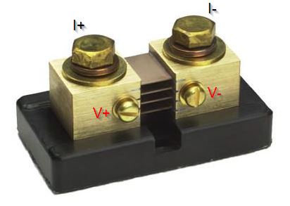
A photo of a 4-terminal sensor might help.

enter image description here

*Figure 1: A 500 A current shunt with the terminals for the high current lugs on top and small screws for the voltage sensing wires on the side. Image source: Solar Electric.

Voltmeter and wires amperemeter have the same distance respect Resistance Subject. Does it works correctly if 4 wires have different length?

Not a problem - well not for pure resistance anyway. If high frequencies are involved then you will have to address the normal high-frequency losses on cables.

Must the ammeter and voltmeter two both contacts be connected at the same place?

Definitely not. In Figure 1 we can see that they are quite separate. The big advantage here is that the V terminals are inside the I terminals so any contact resistances between the wires, crimps, screws, washers and threaded post are not measured. The V terminals only measure the voltage drop across the shunt.

Does it works if ammeter connector has a distance between ammeter connectors and voltmeter connectors?

No.

Could there be some distance between the connectors and Subject Resistance terminals? or must they be connected close to Subject Resistance terminals?

You can see in the photo that the manufacturers

    • have made the terminal blocks of constant width and the same width as the resitance elements. This will ensure the same voltage gradient across the terminals.
    • have placed the screws closer to the resistance elements to minimise measuring any voltage drop across the brass terminals.

Could anyone clarify when the 4 wires method will totally cancel contacts potential and wire resistance in these three prior indicated situation?

It should be clear now that the 4-wire connection will only measure the voltage drop across the resistance element.

\$\endgroup\$

Your Answer

By clicking “Post Your Answer”, you agree to our terms of service and acknowledge you have read our privacy policy.

Not the answer you're looking for? Browse other questions tagged or ask your own question.