0
\$\begingroup\$

I'm currently trying to design a circuit which controls the input of a receiving module which interprets the current flowing through itself as StateA, StateB or StateC. What the input module does with the states is irrelevant in this matter, since I'm focusing on making these currentStates flexible through a raspberry pi.

Normally this input module is controlled with switches and resistors.

But the control circuit I'm designing needs to be maintained (switched) in software and there can't be any physical switches that need to be pressed. Also, since I want to control which of the current States occur with a raspberry pi, a portion of the circuit will end up running on 5 volts. The input module is supplied with 24 Volts. (range goes from 19 to 27 volts)

Originally I planned to get an Arduino Mega (which then gets its input from a raspberry pi) and with it's ~50 Digital Pins I'd be able to control a relay per State per Input. There are 8 Inputs on the module with 3 States each. That makes 24 Relays with corresponding resistor values. But this turns out to be very ineffective compared to just using resistors with switches.

See the schematics below for clarification:
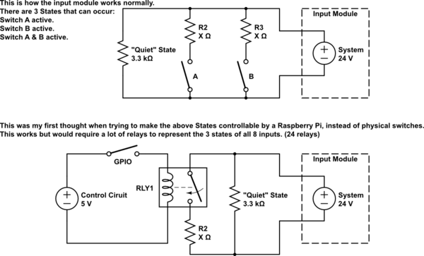
schematic

simulate this circuit – Schematic created using CircuitLab

Is there a different way to provide these 3 "States" with the usage of GPIO? Maybe some sort of switch that is controllable with GPIO?

\$\endgroup\$
4
  • \$\begingroup\$ This would be a whole lot easier if you explain what your circuit is for and how you expect / want it to work. "... a circuit which controls the input of a receiving module which interprets its current as StateA, StateB or StateC" is not normal technical writing. Can you explain this a bit better? Are you trying to make a "software switchable current measurement range select"? \$\endgroup\$
    – Transistor
    Commented May 29, 2019 at 21:18
  • \$\begingroup\$ I updated the question with hopefully better understandable text, if not then please suggest what you would change about the phrasing? Or what you would add to make it more technical? It was my first time asking on this exchange platform and I'm not familiar with asking electronics questions in english. \$\endgroup\$
    – HackXIt
    Commented May 31, 2019 at 8:16
  • \$\begingroup\$ Your English is good but if you add your location into your user profile it helps us understand that English is not your first language and sometimes we can reverse-engineer your writing back to your language to understand what you are asking. You didn't answer my question about what you are trying to make. "Current states" is still confusing. Can you write that part in your own language and maybe someone can improve the translation? \$\endgroup\$
    – Transistor
    Commented May 31, 2019 at 8:44
  • \$\begingroup\$ I updated the question with proper schematics, does that make it understandable? currentStates is just states the circuit can represent in the normal schematic. Either Switch A is pressed, or Switch B is pressed or both are pressed. I called it currentStates because in reality pressing those switches results in a different parallel resistor value and therefor a different current flowing through the module. The module measures these currents and the system behind it interprets them. \$\endgroup\$
    – HackXIt
    Commented May 31, 2019 at 8:51

2 Answers 2

0
\$\begingroup\$

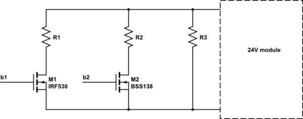
The simplest substitution would be to replace each relay with a MOSFET operating as a switch. I'm assuming that the potential difference across the input pins of your receiver is 24V, in which case you'll want to use a low side switch, using an N-channel MOSFET (or NMOS for short), rather than a high side switch as you drew in your original schematic.

schematic

simulate this circuit – Schematic created using CircuitLab

You'll need to find an NMOS transistor with a low enough threshold voltage to turn on with a 5V gate drive, as well as a low enough RDSon and capability to handle the current you need.

Since you didn't specify how much current each state is, I'll assume they are quite small (few mA or less). The BSS138 is an individual NMOS transistor that can handle up to 200mA drain current with RDSon=6Ω at 4.5V gate drive. Since you'll need quite a few of these, you could also get multiple transistors on a single chip, such as TPL7407LA-Q1.

If you want to control many switches with as few GPIO pins as possible on your microcontroller, you can use a shift register with open drain outputs (which allow the shift register to perform low side switching), such as TPIC6C596. Rather than using a GPIO pin to switch each transistor, you send serial data to the shift register using only SRCK (clock) and SER IN (data) pins, and then update the states of the switches by pulsing the RCK pin. Each shift register has 8 output switches, but you can daisy chain many shift registers together to be controlled with the same serial signals.

\$\endgroup\$
8
  • \$\begingroup\$ The current of each state is lower than 30mA in total (you were right), as of now I'm not sure about the exact current, I'll update the question once I have access to the module datasheet again. \$\endgroup\$
    – HackXIt
    Commented May 29, 2019 at 20:49
  • \$\begingroup\$ The three parts I mentioned should have no problem handling 30mA! \$\endgroup\$
    – wlmeng11
    Commented May 29, 2019 at 21:08
  • \$\begingroup\$ Since you already have a Raspberry Pi in your system, you can use the TLC6C598-Q1 (ti.com/lit/ds/symlink/tlc6c598-q1.pdf) shift register, which can be controlled by 3.3V logic, and switch up to 50mA per output. This would only require a few GPIO pins on the RPi, and eliminate the Arduino entirely. \$\endgroup\$
    – wlmeng11
    Commented May 29, 2019 at 21:12
  • \$\begingroup\$ Yea you're right, that would save this project about 40€, thank you very much.. I still need to look into this though, I'm very unfamiliar with MOSFET. \$\endgroup\$
    – HackXIt
    Commented May 29, 2019 at 21:13
  • \$\begingroup\$ Here are some tutorials on MOSFET as a switch (electronics-tutorials.ws/transistor/tran_7.html), open collector (en.wikipedia.org/wiki/Open_collector) which is the equivalent of open drain for bipolar transistors, and shift registers (electronics-tutorials.ws/sequential/seq_5.html). \$\endgroup\$
    – wlmeng11
    Commented May 29, 2019 at 21:20
0
\$\begingroup\$

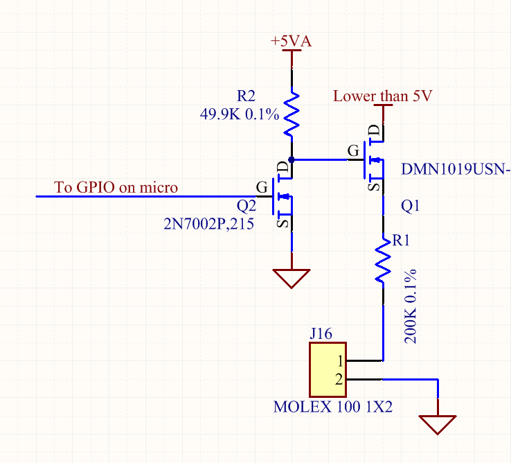
This is a good circuit for switching resistances. The gotcha is the gate level of Q1 needs to be higher than the drain so this circuit is only useful if you have a rail that is higher than the one you are switching.

enter image description here

\$\endgroup\$
8
  • \$\begingroup\$ Sorry, but by rail you mean supply? \$\endgroup\$
    – HackXIt
    Commented May 29, 2019 at 20:26
  • \$\begingroup\$ I don't think this will work in my 5V (Arduino) to 24V (Input Module) scenario, or at least I don't see how it will work for switching resistances. \$\endgroup\$
    – HackXIt
    Commented May 29, 2019 at 20:31
  • \$\begingroup\$ What voltage rails are available to you? What is the voltage range of the input module? \$\endgroup\$
    – Voltage Spike
    Commented May 29, 2019 at 20:39
  • \$\begingroup\$ ~17 to 27 Volts. But the voltage rail of the input module would be at the highest level, or at least it won't be possible to lower it's voltage. \$\endgroup\$
    – HackXIt
    Commented May 29, 2019 at 20:43
  • \$\begingroup\$ Is 27V the highest voltage in the system? \$\endgroup\$
    – Voltage Spike
    Commented May 29, 2019 at 20:49

Your Answer

By clicking “Post Your Answer”, you agree to our terms of service and acknowledge you have read our privacy policy.

Not the answer you're looking for? Browse other questions tagged or ask your own question.