Can anybody help me understand, what exactly a high side and low side driver is? In which scenario would either of them be used?
-
\$\begingroup\$ What research have you done so far yourself? \$\endgroup\$– Nick AlexeevCommented Sep 3, 2015 at 4:56
-
\$\begingroup\$ Nthng much . It is part f mini prjct.. I ws instructed i hav 2 use these drivers for switching.. As f nw i dnt hav any basics in dis... pls help me \$\endgroup\$– AshokCommented Sep 3, 2015 at 5:00
-
5\$\begingroup\$ @Ashok we can't understand you, please speak English. Its borderline rude to try and text here. Be professional \$\endgroup\$– Voltage Spike ♦Commented Oct 17, 2017 at 15:31
1 Answer
In a low-side switch, shown on the left, the load is between the power rail and the N-channel MOSFET doing the switching.
In a high-side switch, shown on the right, the load is between ground and the P-channel MOSFET doing the switching.
The low-side switches are convenient for driving LEDs, relays, motors etc. because you can generally driven them directly from a microcontroller's output, as long as the V\$_{GS}\$ value of the MOSFET is lower than the output voltage of the pin.
If you are using it to drive an inductive load such as a relay or motor, make sure to put a suppression diode across the load.
However they are not so good at supplying power to other circuits, because the ground reference for the driven circuit will be above the real ground by whatever the voltage drop through the MOSFET is.
The high-side switches are better for turning power rails on and off. Because of the pull-up resistor, they are usually driven by an output pin configured as an open-drain (OD). The logic is backwards however; to turn the MOSFET on, you put a ground on the gate. To turn it off, you leave the pin floating as the pullup resistor will keep the MOSFET off. (In the microcontroller, with an OD output, this is done by sending a 1 to the output pin).
There is a gotcha with the high-side switch; if the V\$_{DD}\$ feeding into the MOSFET is more than about 0.6v higher than the supply voltage for the microcontroller, it can damage the latter. This would occur, for example if you are running a microcontroller at 5V and are switching 12V with the high-side switch. In this case, you can use a small N-channel MOSFET, whose output feeds the gate of the P-channel.
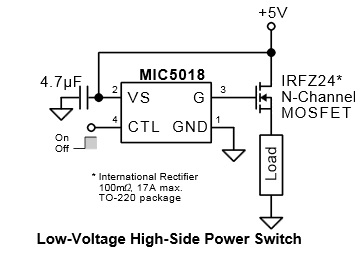
Sometimes it's necessary to switch tens or hundreds of amperes. In this case you can't connect up a N-channel gate directly to a microcontroller output pin, as it will not have enough drive to quickly switch the MOSFET on. So one can use a MOSFET gate driver such as the Micrel MIC5018.
This allows a N-channel MOSFET to be used as a high-side switch. N-channel is preferred over P-channel in high current applications since its on resistance (R\$_{DSON}\$) is lower. Since the gate of the MOSFET has to be V\$_{GS}\$ volts higher than the source, a special IC is needed to translate the logic level at the CTL lead into the much higher gate voltage.
Even if the N-channel was being used in a low-side configuration, the driver chip would be needed to properly drive the gate fast enough. It is also likely that the V\$_{GS}\$ value of the MOSFET is greater then the output of the microcontroller.
-
\$\begingroup\$ This is good.. can u please help me with WHY dey r used simultaneously in a ckt..? like wherever u use a high side does that mean u hav 2 use low side also?/.. \$\endgroup\$– AshokCommented Sep 3, 2015 at 5:21
-
13\$\begingroup\$ First of all, please don't use all those abbreviations in your comments. We're not texting here. You use either a high-side switch or a low-side switch depending on the criteria I gave. You don't have to use both in a circuit. \$\endgroup\$– tcrosleyCommented Sep 3, 2015 at 5:34
-
\$\begingroup\$ Sorry, didnt mean to .. So when you use a high side driver to switch and connect the switch to a load,the negative of the load is connected to the ground? \$\endgroup\$– AshokCommented Sep 3, 2015 at 5:48
-
\$\begingroup\$ Yes, just like the right side of my diagram. \$\endgroup\$– tcrosleyCommented Sep 3, 2015 at 5:52
-
3\$\begingroup\$ @tcrosley, can you please expound upon this statement you said please, and draw a schematic of it? "In this case, you can use a small N-channel MOSFET, whose output feeds the gate of the P-channel." I'm trying to understand how this works. It sounds like when the microcontroller drives the small N-channel MOSFET gate HIGH, the output to the other gate will be small, ~ 3V perhaps, but when the micro drives the small N-channel gate LOW, the output is cut off, and the pullup on the large MOSFET pulls it up to VDD. Is this right? Some extra info on this in your answer would be greatly appreciated! \$\endgroup\$ Commented Feb 7, 2018 at 18:08


