4
\$\begingroup\$

I am driving a red LED with a forward voltage of approx. 2 V as shown in the picture. The driving signal comes from a microcontroller with a logic HIGH of 1.8 V. The LED is being sourced from an independent supply of 3.3 V. The circuit works, but there is something in my measurements that I can't explain.

I measured 3 mA through the LED branch. I need more current through the LED (about 10 mA would be ideal). Then I reduced R1 in steps until I had about 10 Ω, yet the current in the LED did not change much. Sometimes I measured about 8 mA at the beginning of the measurement which after some seconds ended up at 4 mA.

  • Why is this happening? I also reduced R2 but it seems to have no effect either.

  • How could I increase the LED using a control signal of 1.8 V and powering the LED with 3.3 V?
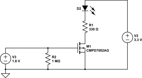
schematic

simulate this circuit – Schematic created using CircuitLab

\$\endgroup\$
6
  • \$\begingroup\$ got a link to the data sheet of your mosfet? \$\endgroup\$ Jun 14, 2019 at 15:22
  • 1
    \$\begingroup\$ It seems to have something to do with maybe some current limit on the mosfet, or its internal resistance. I wasn't able to find its datasheet by the model specified on the circuit... Can you provide one? \$\endgroup\$
    – Iaka Noe
    Jun 14, 2019 at 15:22
  • 4
    \$\begingroup\$ I'm pretty sure the answer is in the datasheet for the MOSFET. Provide a link to it, please. \$\endgroup\$ Jun 14, 2019 at 15:24
  • 1
    \$\begingroup\$ If you want a direction what voltage you need to decently drive a mosfet: do not be guided by Gate Threshold Voltage \$V_{GS(th)}\$, but check the Test Conditions given by the Static Drain–Source On–Resistance \$R_{DS(ON)}\$. \$\endgroup\$
    – Huisman
    Jun 14, 2019 at 15:51
  • \$\begingroup\$ please do not post a screen shot of the schematic ... the schematic editor adds the schematic to the post when you save the schematic .. \$\endgroup\$
    – jsotola
    Jun 14, 2019 at 19:03

4 Answers 4

2
\$\begingroup\$

The problem is most likely that the mosfet does not have enough voltage to fully turn on. Vgs is probably not high enough. I couldn't find the datasheet for the CMPD7002 (or any part named that). First make sure the Vgs will give you enough current, find how much Vgs you need for the Rds on. You'll need to do one or more of these things:

1) If the GPIO's on the microcontroller are 3.3V tolerant (or if 3.3V is fine with a pull down) Then use open drain on the GPIO and a pull up to 3.3V

2) Use a circuit or buffer to translate 1.8 to 3.3V

3) Select a different mosfet that turns on at 1.8V and has a low rdson at 1.8V.

4) Calculate the current vs LED drop and size R1 correctly.

\$\endgroup\$
2
\$\begingroup\$

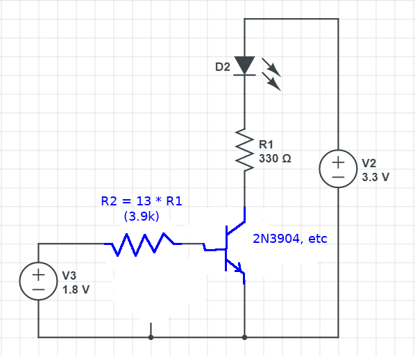
Use a good ol' BJT, or find a logic-level FET rated for 1.8V. I've called out a 2N3904 in the suggested schematic below, but (A) you can use just about any small-signal NPN there, and (B) there are prebiased transistors that'll work and save you a resistor.

Design for an 0.7V drop from base to emitter, and a base current of about 1/10 of your desired collector current, to keep the transistor hard into saturation.

enter image description here

\$\endgroup\$
3
  • \$\begingroup\$ This should be good for 3mA if R2 =13*R1 *1.8/3.3 \$\endgroup\$ Jun 14, 2019 at 18:41
  • \$\begingroup\$ I'm not sure what you're trying to say. The collector current is (3.3V - 2V)/R1; the base current is (1.8V - 0.7V)/R2. The base current needs to be 1/10 the collector current, and I rounded the V3-base voltage to 1V -- so R2 = 10 * (1.3V)/(1V) * ) * R1 = 13*R1 more than satisfies the rule of thumb for base current in a saturated transistor. If the OP wants more current, then they need to reduce R1, and then R2 to match (while observing the current source capability of the pin they're driving the gate with). \$\endgroup\$
    – TimWescott
    Jun 14, 2019 at 19:22
  • \$\begingroup\$ Ic=(3.3-Vf-Vce)/330=3.6mA if Vce=0.1 when Ib= 364uA with (1.8-0.7)/364uA= 3k so R2/R1= 6.06 \$\endgroup\$ Jun 14, 2019 at 19:31
1
\$\begingroup\$

You need a MOSFET that turns on fully with 1.8V. Not many will. Do you have a datasheet for CMPD7002AG? I'm not getting any hits on it.

This one looks like it will turn fully with just 0.9V on the gate

https://www.onsemi.com/pub/Collateral/MCH3484-D.PDF

Digikey has them.

\$\endgroup\$
2
  • \$\begingroup\$ Hi, this is the datasheet: eu.mouser.com/datasheet/2/68/cmpdm7002a-25208.pdf It is strange that it is not being shown on the search results. According to it the VGS (Threshold) can be as low as 1 V. This is the parameter I used to pick this MOSFET but maybe I misinterpreted other parameters. Is it incorrect to assume that once Vgs is bigger than its threshold value the MOSFET is fully ON? Thanks \$\endgroup\$
    – Daniel
    Jun 17, 2019 at 8:23
  • \$\begingroup\$ The range of the threshold voltage is from 1V for some of them to 2.5V for others of them. The DS Mosfet current at its threshold voltage is only 250 micro-amps which is almost turned off. Buy hundreds of them and test them all then maybe you will find one that is more sensitive than the one you have. \$\endgroup\$
    – Audioguru
    Sep 8, 2022 at 1:18
0
\$\begingroup\$

Although you have not linked any part numbers, I suspect you can drive the 2V LED Cathode directly from Vol with Anode to 3.3. The Ron= Vol/Iol should be in the 50 Ohm ballpark. Then when High , the LED will see 3.3-1.8 = 1.5V which will be very dim.

All you need is 10mA so when ON, the driver will rise to 3.3-2V= 1.1V with a current of 1.1V/50R or 22mA so adding 50 R in series will reduce the current to ~ 10mA and Vol to 0.6V .

For protection (opt.) in case of 3.3 rising before 1.8, just add a Schottky diode from output port to Vdd.

Then you need to invert the LED state in S/W.

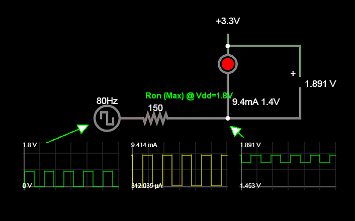
Proof with Sim and specs

From Cypress datasheet p76
Iol = 4 mA at Vdd=1.8V Vol = 0.6 max, thus driver Ron= Vol/Iol=0.6V/4mA = 150 Ohms
enter image description here

I used a custom model of Vf=2.1V @ 20mA ( Isat=92pA, ESR 12 Ohms, Emission coefficent =3.73, breakdown voltage= 2V)

The above simulates minimum current from an ARM Core data port using 1.8V supply.

Adding 150 OHms will reduce brightness in half to 5mA min.

\$\endgroup\$

Your Answer

By clicking “Post Your Answer”, you agree to our terms of service and acknowledge you have read our privacy policy.

Not the answer you're looking for? Browse other questions tagged or ask your own question.